- Home
- Forums
- NAXJA Unibody Jeep Technical Forums
- Jeep Cherokee XJ (1984 - 2001)
- Modified Tech Discussion
You are using an out of date browser. It may not display this or other websites correctly.
You should upgrade or use an alternative browser.
You should upgrade or use an alternative browser.
My FitchBox (tm)
- Thread starter splitz
- Start date
Brendan_91XJ
NAXJA Member #1163
- Location
- Long Beach, CA
splitz said:Yeah, its nice to see a thread I started actually go beyond a page!
And still alive for 8, going on 9 months.

Wallymander
NAXJA Forum User
- Location
- OKC
splitz said:I think you are correct. The ground is only for the coil, since the high current return would be done via the ground on the light (or what ever).
What I did was line up my grounds so I could use the right angle terminals to daisy chain them. Look at the second pic on the first page. You can see the black wire on the outside track going from one terminal to the next.
To be a geek, according to electron flow theory, they (electrons) flow from negative to positive. FWIW. there, now i feel smart.
Wallymander
NAXJA Forum User
- Location
- OKC
Oh yes, did anyone consider a DB-9 connector and serial cable in the place of the 8- pin modular? just a thought. I like the screw posts on a db9, a little more secure and less prone to corrosion. And you can get one more conductor, not there is any room for another relay in there anywhere.
- Location
- Houston, Tx
Ok... I dont know a thing about cat-5
can someone explain how the cat 5 works to me? are you linking the same wire within the cat 5 on both ends?
can someone explain how the cat 5 works to me? are you linking the same wire within the cat 5 on both ends?
Wallymander said:Oh yes, did anyone consider a DB-9 connector and serial cable in the place of the 8- pin modular? just a thought. I like the screw posts on a db9, a little more secure and less prone to corrosion. And you can get one more conductor, not there is any room for another relay in there anywhere.
That's an interesting idea. I like the security of the screw terminals, plus the added bonus of corrosion resistance. The only reason I wouldn't is because I like the smaller form factor of RJ-45.
IslanderOffRoad said:Ok... I dont know a thing about cat-5
can someone explain how the cat 5 works to me? are you linking the same wire within the cat 5 on both ends?
Cat 5 is a type of copper cabling that utilizes four twisted pairs in one sheath. Yes, we are using the same conductor on both ends.
- Location
- Houston, Tx
splitz said:Cat 5 is a type of copper cabling that utilizes four twisted pairs in one sheath. Yes, we are using the same conductor on both ends.
so if you are plugging it in on one end, and splicing on the other, are the cables always in the same config? or does it take some trial/error to figure out which one is going where?
Stallacrew
NAXJA Forum User
- Location
- Cullman, Alabama
They are color coded Green, Blue, Orange and Brown with a white version of those colors with a colored tracer. You wire it the same on both sides and hook it up accordingly to your switches.
Blue to a light's relay, then blue to the lights switch. Super easy.
I don't think it matters with them cross talking. It'd be the same as just running 8 individual wires from the relay box to the switches, only this way they are handily contained in a commn sleeve.
Blue to a light's relay, then blue to the lights switch. Super easy.
I don't think it matters with them cross talking. It'd be the same as just running 8 individual wires from the relay box to the switches, only this way they are handily contained in a commn sleeve.
- Location
- Houston, Tx
Ok, I suck at electrical so I was just trying to figure it out. I like the idea alot and will be looking into it.
scott00tj
NAXJA Forum User
- Location
- Medina, OH
I like the idea of using Cat5. I'll keep that in mind with my next round of wiring.
scott00tj said:I like the idea of using Cat5. I'll keep that in mind with my next round of wiring.
remember it is only for low amp circuits. Cat5 is like 24awg, so if you use it on for high current applications, you will have a firey situation.
xSUx SGT BAKER
NAXJA Forum User
- Location
- Michigan
im in the process of building my own FitchBox (tm), and i happened to run across a usb attachment from an old motherboard i had. It has 8 wires that you can use for signal (4 on each usb connection). I just figured i would throw it out there as another substitute for the cat5 cable, although im still deciding between the two. Thanks to everyone that contributed to this thread and to FitchVA for all the ideas")
selarep
NAXJA Forum User
- Location
- Central CA
im in the process of building my own FitchBox (tm), and i happened to run across a usb attachment from an old motherboard i had. It has 8 wires that you can use for signal (4 on each usb connection). I just figured i would throw it out there as another substitute for the cat5 cable, although im still deciding between the two. Thanks to everyone that contributed to this thread and to FitchVA for all the ideas
Post some pics!
xSUx SGT BAKER
NAXJA Forum User
- Location
- Michigan
Well, i'm not very far. I have the project box and a fuse block, and it was just today that i was scrounging through my room when i came across the usb connector :doh: But i will post progress pics as i get things done on it :wave:
Here is a pic of the usb connector.

I know I have a cat5 socket around the house somewhere, when I do find it i will post some size comparison pics. Im kind of leaning toward the usb connectors at the moment, but I will make a decision for sure when I see the size of the cat5 socket :chef:. Also, I plan on using DanMan2k06's idea with the studs to connect the power to my accessories.
On a side note, bussman sells inline fuse holders (http://host1.publiquik.com/bussmann_web/family.cgi?familyUid=82 this one specifically), they are rated up to 30 amps and they use 12 awg wire. So.. I was wondering why some people are using 10 awg wire if the relays are only good up to 30 amps (i am no electrical genious lol:gag") ?
?
edit: sorry for the pic size
Here is a pic of the usb connector.
I know I have a cat5 socket around the house somewhere, when I do find it i will post some size comparison pics. Im kind of leaning toward the usb connectors at the moment, but I will make a decision for sure when I see the size of the cat5 socket :chef:. Also, I plan on using DanMan2k06's idea with the studs to connect the power to my accessories.
On a side note, bussman sells inline fuse holders (http://host1.publiquik.com/bussmann_web/family.cgi?familyUid=82 this one specifically), they are rated up to 30 amps and they use 12 awg wire. So.. I was wondering why some people are using 10 awg wire if the relays are only good up to 30 amps (i am no electrical genious lol:gag
?edit: sorry for the pic size
Heathdude
NAXJA Forum User
- Location
- Bagdad, AZ
Here's a couple links for figuring out who, what, how much and so on...
http://www.onlineconversion.com/ohms_law.htm
http://www.powerstream.com/Wire_Size.htm
So figuring 130W x 2 = 260W. I'll add 10% for a forgivness factor and get 286W. Plug in the other known factor, 12V. So you get the magic number of 23.83 amps. Heck, let just round up to 25 amps for giggles. It don't hurt to go bigger or burn to the ground.
So now I've got 25 amps that I'm going to run about 6 feet. I'll be coming of of the relay with two wires, one for each light. Trying to keep the voltage drop low enough, I'd run a minimum of 12 AWG. That would drop about .25 volts over the length of the run. I'd prefer to 8AWG, but that's a lot of big holes to poke in the roof.
Now you can spend endless hours playing with numbers and be as geeky as I am.
xSUx SGT BAKER
NAXJA Forum User
- Location
- Michigan
i planed on running larger gauge wire all the way to the box, and on the outside of the box. But just for the short distance that is inside the box, would it really be unsafe to run 12 awg wire?
you can run 8 switches on cat5, and 4 one USB. once you cram power, dim, signal and ground in the A pillar, you won't want to cram a second signal wire in there. plus you can't exactly do a cut to fit USB custom cable.im in the process of building my own FitchBox (tm), and i happened to run across a usb attachment from an old motherboard i had. It has 8 wires that you can use for signal (4 on each usb connection). I just figured i would throw it out there as another substitute for the cat5 cable, although im still deciding between the two. Thanks to everyone that contributed to this thread and to FitchVA for all the ideas
not saying it is a bad idea, but i had a hard enough time squeezing those 4 wires up in there. i still have to pull it all apart again and bundle it nice so the trim goes back on correctly.
no "latching" connection with USB either
xSUx SGT BAKER
NAXJA Forum User
- Location
- Michigan
:doh: i thought it was 6 with cat5 cable. well i guess that makes my mind up, i'm going with cat5.
Heres some pics of my box so far. Mine is mounted under the hood so I put my headlight relays in the box as well. RIght now its only running my high and low beams, but the fog relay is wired just need to instal the fogs. Once spring gets here my Hella 500's will be run thru it as well. After getting this far I realized I really needed a larger project box.


smccollamjr
NAXJA Forum User
- Location
- WV
Here my latest version of the "FitchBox"

Here is my current switch panel:
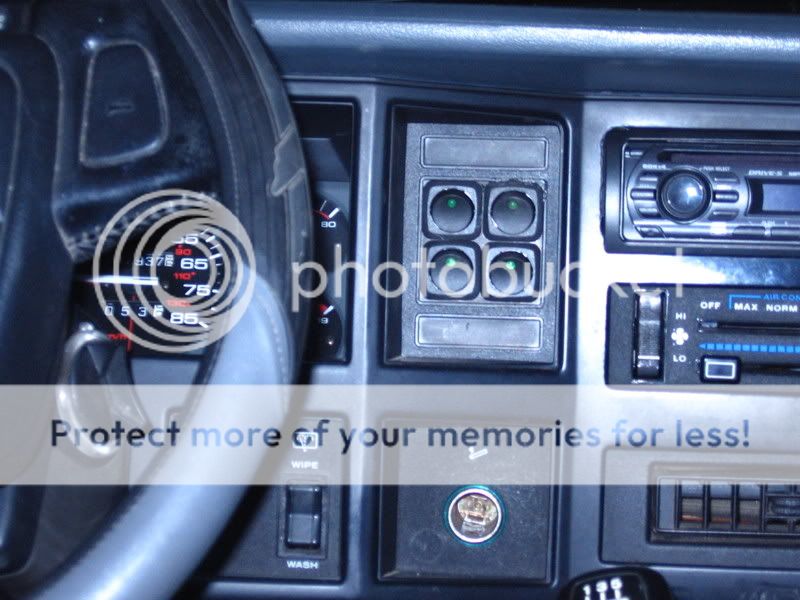
Here is my current switch panel:
Similar threads
- Replies
- 3
- Views
- 326
- Replies
- 11
- Views
- 505
- Replies
- 3
- Views
- 342