• Welcome to the new NAXJA Forum! If your password does not work, please use "Forgot your password?" link on the log-in page. Please feel free to reach out to [email protected] if we can provide any assistance.

CAN bus to CCD bus Protocol Translator(Chrysler PCM Simulator)

Alexia

NAXJA Forum User
Location
Huntsville, AL
I am working on a new project lately to be able to drop a Haltech Elite ECU into my 1997 based MJ without losing the stock gauges or other CCD bus operated modules. This is accomplished by translating CAN bus messages from the Haltech into CCD bus messages simulating the stock Chrysler PCM. It removes the need to keep the stock PCM in place to run any systems and removes wiring/sensor complexity from running two engine computers. As well, this would simplify any CAN bus controlled engine swap, such as a GM V8, by only needing to plug in a little box between the data lines to retain the stock gauge cluster.

Current implementation status:
  • Chrysler CCD bus Packet IDs - Only missing fuel level. Everything else works including odometer/tripometer incrementing.
  • Haltech CAN - In progress - Haltech is kind enough to provide full documentation to anyone that asks. Needs quality assurance testing and validation on my MJ when the wiring is finished.
  • GM CAN(GMLAN) - I have a copy of the GMLan Bible. I would need to obtain an GM ECU or borrow a GM swapped vehicle for a few weeks. Otherwise implementing GM support will be as easy as Haltech support.

Example of controlling the gauge cluster over USB.

uFLohjA.jpg


Testing how fast the gauge cluster can respond to data packets. The needles visibly stop moving when hitting the processing limits of the gauge cluster's microcontroller. The fastest I can get the gauge cluster to respond is 20hz or one update every 50ms. This might actually be faster than how fast the stock PCM updates.

l41YnDZmPKtzUkjks.gif
 
Awesome!
Back when I dyno'd 193whp and 231wtq, the shop wanted me to buy the Haltech standalone ecu because the stock pcm was lean. I love watching MCM with the Haltech guru.


Sent from my iPhone using Tapatalk
 
Last edited:
Awesome!
Back when I dyno'd 193whp and 231wtq, the shop wanted me to buy the Haltech standalone ecu because the stock pcm was lean. I love watching MCM with the Haltech guru.


Sent from my iPhone using Tapatalk

That is part of the problem I having now and why I am doing all this to switch. The stock PCM will be fine, then lean out, and then suddenly go balls to the wall dumping fuel in trying to correct it. Waiting for one of the two tuners in the USA who know how to flash JTEC PCMs, plus the cost, is not worth it in comparison to the cost and flexibility of an aftermarket ECU.
 
Do you have any technical details? I have been working on something like this for a TDI swap, and there's also a thread on thespeedfreaks.net that I've been following. Id love to help, as this is something I've been working on in the background for almost a year now. You've made it further than I have, seeing as how you have moving needles.
 
Do you have any technical details? I have been working on something like this for a TDI swap, and there's also a thread on thespeedfreaks.net that I've been following. Id love to help, as this is something I've been working on in the background for almost a year now. You've made it further than I have, seeing as how you have moving needles.

Repository is right here:
https://github.com/Alexia/CAN-CCD_bus

I have an unpushed branch with more Haltech CAN bus work on my laptop, but I am waiting to push it until I have it tested on my MJ. Which is waiting for my slush fund to recover to make a part purchase since I am about to drop several thousand in repairs on my LJ.
 
How are you driving the CCD bus? Are you using any of the older SPI to CCD
Intersil chips or driving it directly with the teensy? Ill pull your code when I get home, it looks great!
 
Oh, you were looking for fuel level? The link I dropped earlier has documented the fuel CCD address for a Durango.

// Fuel ID 37 [HEX-25] (ID-DATA-CRC)
// DATA range 1 ~ 253 + Error handling.
 
How are you driving the CCD bus? Are you using any of the older SPI to CCD
Intersil chips or driving it directly with the teensy? Ill pull your code when I get home, it looks great!

Teensy is handling the serial level logic to a CAN bus transceiver. Yes, the CAN bus transceiver is being used to drive the CCD bus.

Oh, you were looking for fuel level? The link I dropped earlier has documented the fuel CCD address for a Durango.

// Fuel ID 37 [HEX-25] (ID-DATA-CRC)
// DATA range 1 ~ 253 + Error handling.

I have been trying 0x25, but none of the values I looped through have made the XJ gauge cluster respond to it yet.
 
I finally got home from work and got a chance to clone your repo. I'm looking at CCD::doUpdateLights() and I noticed you set the airbag status. In my engine swap, I was planning on retaining all of the CCD modules (OHC, airbag, gauges) so I am more concerned with emulating the messages provided by the ECU than anything else. Since I plan on retaining the airbag controller, I would be concerned about leaving it on the CCD bus if the address used for airbag status is shared with your code. Is this message provided by the ECU or by the airbag controller?

Either way, I like what you have here. I was going the approach of using an Intersil CCD chip over SPI. Your approach of using a CAN transceiver and handling the rest in code seems to actually involve fewer IOs, less interrupts, and has a lower component count. Do you think there is potential for bidirectional communication with your approach of using a CAN transceiver as the physical interface?

Do you have anything you would like help with on this project?
 
Last edited:
I finally got home from work and got a chance to clone your repo. I'm looking at CCD::doUpdateLights() and I noticed you set the airbag status. In my engine swap, I was planning on retaining all of the CCD modules (OHC, airbag, gauges) so I am more concerned with emulating the messages provided by the ECU than anything else. Since I plan on retaining the airbag controller, I woulc be concerned about leaving it on the CCD bus if the address used for airbag status is shared with your code. Is this message provided by the ECU or by the airbag controller?

Either way, I like what you have here. I was going the approach of using an Intersil CCD chip over SPI. Your approach of using a CAN transceiver and handling the rest in code seems to actually involve fewer IOs, less interrupts, and has a lower component count. Do you think there is potential for bidirectional communication with your approach of using a CAN transceiver as the physical interface?

Do you have anything you would like help with on this project?

Setting/changing the air bag light status is purely optional. My eventual plan is to have a build system where people type in their platform code, what modules they are retaining, and other options. So if someone selects "no air bag module" it would compile the firmware to turn off the air bag light so they don't see it turned on in the dash.

The CAN transceiver I am using does not work to receive on the CCD bus. It applies power the CCD bus, but CCD is designed to be powered from one source. In the case of the XJ the power source is the gauge cluster.

I actually want to rework the code slightly to use a middleware style so that messages broadcasted on one bus are reflected to any bus. The first iteration will be purely one way CAN to CCD.
 
Oh, you were looking for fuel level? The link I dropped earlier has documented the fuel CCD address for a Durango.

// Fuel ID 37 [HEX-25] (ID-DATA-CRC)
// DATA range 1 ~ 253 + Error handling.

BOOOOOOOOOOOOOOOYAH THAT WORKS! Every time I tested 0x25 for a packet ID I had been using 0x00 or 0xFF. Which is empty and open circuit which displays empty. However, whenever testing other values I would start with 0x00 then set it higher. Since the XJ gauge cluster buffers that value automatically it can take five to ten minutes to reach that new point. Patience in testing never came to mind in that case.
 
BOOOOOOOOOOOOOOOYAH THAT WORKS! Every time I tested 0x25 for a packet ID I had been using 0x00 or 0xFF. Which is empty and open circuit which displays empty. However, whenever testing other values I would start with 0x00 then set it higher. Since the XJ gauge cluster buffers that value automatically it can take five to ten minutes to reach that new point. Patience in testing never came to mind in that case.

That's great news! The same post indicated that the low fuel light was a fixed range of the fuel level (0x35 - 0x01), not programmable. When you indicate a low level, does the fuel light Illuminate?
 
That's great news! The same post indicated that the low fuel light was a fixed range of the fuel level (0x35 - 0x01), not programmable. When you indicate a low level, does the fuel light Illuminate?

I did not test the exact values, but the light does turn on automatically after a ten second delay in the expected low fuel range.
 
VERY cool.

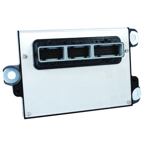
I have a couple of aftermarket ecus and access to some others that use the same form factor as the stock ECU......but are fully programmable and configurable....and talk CANBUS.

ECU555-80.jpg


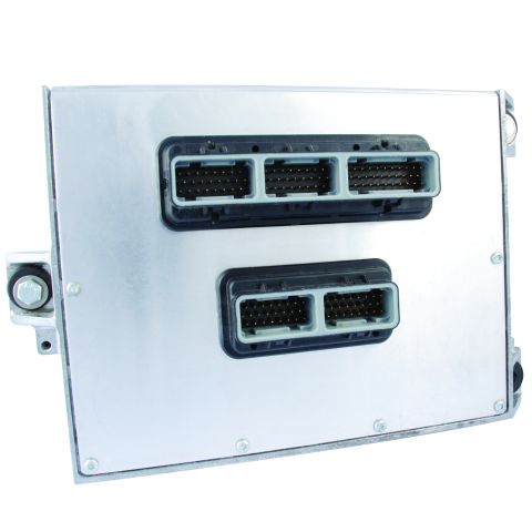
128pin version:

ECu565-128.jpg


Now thats great for using those, but you come onto a good use as well, the diesel KJ ecu runs on canbus, so to spit out data for the CCD bus is perfect.

Alternatively I could use TJ PCI cluster.....I think one of these should work.
 
The CAN transceiver I am using does not work to receive on the CCD bus.

So I've been reading datasheets for the MCP2551 and the SN65HVD230, both look like they are capable of providing a physical interface capable of receiving on a CCD bus. When I look at the architecture diagram of the Intersil CPD68HC68S1, the CAN differential receiver implements similar function, minus arbitration detection, collision detection and idle detection. Outside of your published code, have you attempted to monitor the RxD pin while transmitting? I have a SN65HVD230 coming snail mail, so I cannot test this theory for myself.

I think the function of the Intersil could be implemented in software, bringing duplex communication into your project. Arbitration detection, collision detection and idle detection all are well documented in the CPD68HC68S1 datasheet, I just don't think I am up to the task of implementing them.

The receive pin just shows a reflection of whatever is being transmitted currently. Outside of that it never shows anything even when something else on the bus is transmitting.
 
Awesome! Just awesome, really impressive and thanks for sharing! I've been working on an LSx swap into my 01 XJ and this is exactly what I want to do. Only difference is I am using the GM red/blue 411 PCM which uses J1850 instead of CAN. I originally planned to drive stock Instrument Cluster by retaining Jeep PCM and using discrete sensor inputs for oil pressure, coolant temp and speedometer. Also have the Novak Tachometer module to generate CPS signal on Jeep computer. For Cruise and Check Engine Lights I used little 194 Bulb sockets with pigtails and control them separately. All of this works decently enough and works like factory, but ends up being a lot of extra wiring and complexity. Your post gives me enough confidence to scrap all of that and just move forward with an integrated solution.

I got up and running with your code on the Teensy and Waveshare CAN quickly enough - couple of observations and questions for you?

1) Airbag light stays on, looks like code is setup to turn on/off but I don't see any changes in the status light. I am keeping the Airbag module but was testing on the bench.

2) Speedometer is working but I don't see Trip or Odometer incrementing. I saw you mention your code supported this but didn't see anything? Can you describe a little bit how this works? I would have expected the IC to increment odometer itself just based on speed inputs.

3) Looks like logic for 4 smaller gauges only updates if values change? I suppose in real world these would always be changing, but on the bench it seems these messages only get sent the very 1st time. Unless the IC is powered up before Teensy, it will miss the initial messages and never update the gauges. Makes me curious how factory PCM handles this, do you think it uses CCD BUS Ack's to know if messages were properly received or not? Perhaps, sending these messages periodically even if they aren't updated would help with prototyping?

4) I tried an MCP2551 CAN Transceiver @ 5v. Seemed to work just fine, instrument panel output was the same. Any particular preference to the 3.3 Waveshare module you are using?


Thanks!

CJ

IMG_8195.jpg
 
Last edited:
Wanted to share some info that might be useful for others working on the power train wiring. Eliminating the factory ECU does present some other challenges with regard to integrating a different control module with the rest of the vehicle. Hope you don't mind this in your thread Alexia!

I searched a long time to find Factory PCM Plugs. What I really wanted was a male version so I could make a "plug and play" harness that doesn't modify the vehicle body / chassis harness. In the end, you can get replacement female plugs from Mopar but they are a bit pricey, around $30/ea if I recall. You can see part numbers in pic below. I never did find any male versions, short of people who hacked an old JTEC PCM to steal the connector. It doesn't look like a very clean or sustainable solution so I scratched that idea.

The connectors are/were manufactured by TE under the "Super Seal" line. I was able to locate the factory style 32-pin connectors, but none have the correct "keying" to match the factory connectors - I guess these were made specifically for and only supplied to Chrysler. It makes me wonder though, after seeing the link in this thread to other PCMs that look to have same form factor & connectors. If you cut/grind the keys off, this will technically work in the factory PCM:
http://www.mouser.com/ProductDetail/TE-Connectivity/4-1437287-7/

Then, I found a "newer" version of the Super Seal connector, in 26 and 34 positions. Both male/female versions are readily available. I see these commonly used in other PCM applications. Holley is using these on their Dominator EFI system and you can buy some pre-made harnesses from them:
http://www.mouser.com/ProductDetail/TE-Connectivity/6437288-1/
http://www.mouser.com/ProductDetail/TE-Connectivity/571-4-1437290-0/
https://www.holley.com/products/fuel_systems/fuel_injection/dominator_efi/harnesses/parts/558-408
https://www.holley.com/products/fuel_systems/fuel_injection/dominator_efi/harnesses/parts/558-403

The big win though, is that the crimp connectors, the pins inside these connectors are all the same. So, de-pin the factory PCM plug that is part of the body harness. Then, can simply plug those wires into a new Super Seal connector and integrate/build from there with no modification to vehicle wiring.

That Gray C3 PCM connector contains a lot of valuable signal wires. It has the input for cruise control, trigger wires for the relays in factory fuse box like fuel pump and electric fan, connection to the factory CCD bus, brake sensor wiring, etc, etc. I see a lot of people hack up the fuse box, but you can integrate @ C3 and not cut any wires at all.

C107 contains the +12v and chassis grounds to power up "the black box".

Hth,

CJ

c1c2c3c107.jpeg

Jeep-C3.jpeg
 
Last edited:
1) Airbag light stays on, looks like code is setup to turn on/off but I don't see any changes in the status light. I am keeping the Airbag module but was testing on the bench.

1997 clusters need the code sent once at start up to turn it off. 1998-2001 clusters need it periodically sent to keep it turned off. If you have the air bag system in place just keep the air bag module wired into the CCD bus and it will take care of it for you.

2) Speedometer is working but I don't see Trip or Odometer incrementing. I saw you mention your code supported this but didn't see anything? Can you describe a little bit how this works? I would have expected the IC to increment odometer itself just based on speed inputs.

Odometer is incremented by it listening to the DIST_INCR_ID (0x84) code. So the microcontroller has to calculate the distance traveled since the last transmission based on speed and time then send it using 0x84.

3) Looks like logic for 4 smaller gauges only updates if values change? I suppose in real world these would always be changing, but on the bench it seems these messages only get sent the very 1st time. Unless the IC is powered up before Teensy, it will miss the initial messages and never update the gauges. Makes me curious how factory PCM handles this, do you think it uses CCD BUS Ack's to know if messages were properly received or not? Perhaps, sending these messages periodically even if they aren't updated would help with prototyping?

Correct, they update if a new value is transmitted. The speedometer and tachometer will fall back to zero if a new value is not sent every few seconds.

In the stock setup the CCD bus is powered and initialized by the gauge cluster. The PCM will not transmit until it sees voltage on the lines.

The logic I built into the CAN-CDD bus library so far only sends new values for those four gauges when they change or a certain timeout in seconds occurs.(I forget how long that is at the moment.)

4) I tried an MCP2551 CAN Transceiver @ 5v. Seemed to work just fine, instrument panel output was the same. Any particular preference to the 3.3 Waveshare module you are using?

It was cheap and already soldered to a board so I could get right to prototyping.
 
Back
Top