fyrfytr1717
NAXJA Forum User
- Location
- Turlock, CA
I know there are many, many write-ups out there regarding how to override the electric radiator fan, but so far as I've been able to find, this is the first that takes this particular approach. My hands on experience only involves the 1999 model year, but I'd assume this information should apply to all '97-'01 models and most likely (with some adaptation) to earlier years. Take the proper precautions when doing any wiring on your vehicle, especially when it comes to tapping into factory circuits or you may fry your PCM (like I almost did)...
I wanted the PCM to be able to activate the fan as designed, providing a ground signal to the Radiator Fan Relay when coolant temp reaches approximately 218* or A/C is requested. I also wanted to be able to make the fan run continuously. I did not however want to run an additional heavy gauge fused power wire to the fan to make this happen. I figured there had to be a way to take advantage of the factory wiring and fool the system into activating the fan.
I knew I was not alone in this pursuit as I had read many posts about trying this with the outcome being either a CEL or no fan function at all. I had spent way too much time reading through threads and staring at the FSM wiring diagrams and was close to throwing in the towel when a fellow user (MrJCRod) posted up the description of how he had made it work. I turned it into a wiring diagram, researched the location of all the necessary wiring, and decided it looked like it should work. Here's how I went about doing it...
Here's the wiring diagram. It is based upon the FSM wiring diagram, but I did a little cut and paste work on it to show how the wiring needs to be run. Essentially, the wire leading from the PCM (DB/PK) which supplies the ground signal to the Radiator Fan Relay is cut. This wire is re-routed to a New Relay, which in turn supplies a ground signal to activate the old relay. A switch which also provides a ground signal is connected to the old relay as well.
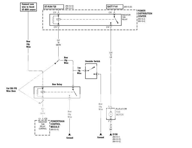
Here's the possible on/off situations that would be faced:
1. PCM off and switch off - new wiring is invisible to the PCM
2. PCM on and switch off - PCM activates new relay which in turn activates fan relay / PCM isolated by new relay
3. PCM off and switch on - switch activates fan relay / PCM isolated by new relay
4. PCM on and switch on - fan relay activated by both new relay and switch / PCM isolated by new relay
So having a wiring diagram is all fine and dandy, but I'm sure you'd rather know how to go about actually wiring this up...
First off, I wired up a switch for the fan override. I located it in my overhead console (along with a bunch of other switches) and routed the signal wire into the engine compartment. Something important to keep in mind here is that you need to set up your switch to provide a ground signal. Mine was originally set up to provide 12V+ so I had to do a little rewiring before I could get started...

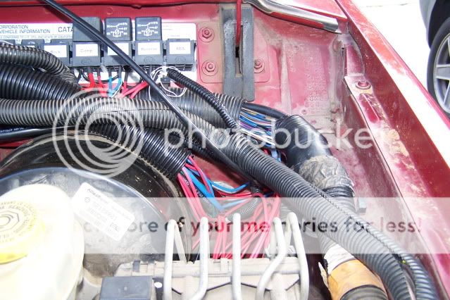
Next up was to find a place to tap into the wiring. After researching the FSM I found that all the necessary wiring ran from the PCM, along the firewall, and into the PDC. My relays are all mounted on the driver's side of the firewall so I chose a convenient spot and removed a few inches of the ribbed wiring loom.
I needed the signal wire for the Radiator Fan Relay and a fused ignition switched 12V+ (ST-RUN) source to simulate the original circuit. The signal wire is Dark Blue w/ Pink tracer and is found in Pin C2 on Connector 3 in the PCM. The ST-RUN wire is Dark Blue w/ White tracer and is found in Pin A2 on Connector 1 in the PCM. I would suggest doing a continuity test between the PCM connectors and the wires you are about to cut/splice so you don't make the same mistakes I did. I found that under fluorescent lighting, the Dark Blue w/ Orange tracer looks an awful lot like the Dark Blue w/ Pink tracer. (This led me to the discovery that it is possible wire up an A/C Compressor Clutch override switch, if you really wanted to...:shhh") I also thought that the DB/WT (one of my favorite wires for a number of other mods I have done) would be pretty straightforward. Unfortunately, as can be seen in the following pic, there is another DB/WT and a DB/GY that run through the harness in this spot which could be easily mistaken for the correct wire.
I also thought that the DB/WT (one of my favorite wires for a number of other mods I have done) would be pretty straightforward. Unfortunately, as can be seen in the following pic, there is another DB/WT and a DB/GY that run through the harness in this spot which could be easily mistaken for the correct wire.
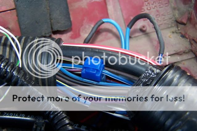
Next, cut the DB/PK wire as shown in the above picture. Attach extension wires onto both ends, each long enough to reach your New Relay. Tap into your (ST-RUN) wire and provide a long enough wire to reach your New Relay as well. You will also need a ground wire leading to your New Relay. Mine is daisy chained from the relay sitting next to it. Make sure your switch's signal wire also reaches the location of your New Relay. Mine is the small gauge white with tan tracer wire shown in the following pic.

Make the connections on your New Relay as follows:
Relay Pin 85 - DB/PK wire coming from your PCM
Relay Pin 86 - DB/WT (ST-RUN) wire
Relay Pin 30 - Ground wire
Relay Pin 87 - DB/PK wire going to the Fan Motor Relay (in the PDC) and the ground signal wire coming from your override switch
Relay Pin 87a - May or may not exist on your relay, but is unused regardless
That's it, that's all there is to it. I've been using mine for a few days now and can confirm that everything works as it should, and there's no CEL! Overall, I'm very satisfied with how this turned out. It takes advantage of the factory harness and requires no new fuses and very little additional wiring. One item to note, if you wire this up as I have detailed and use a lighted switch, the indicator light on the switch will come on every time the Radiator Fan Relay kicks on (regardless of the position of the switch). This could be easily prevented, but with my switch installed out of my line of sight it doesn't really bother me. If your switch is mounted on the dash, I imagine it would get pretty annoying (especially at night) when using your A/C as it continuously cycles the fan on and off.
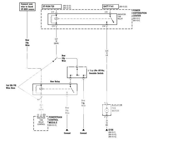
For those of you who not only want to be able to turn your fan on at will, but also want to be able to prevent it from coming on for say water crossings or something, here is the wiring diagram for you. Essentially the same as the diagram above, only you use a 3-Way switch (On-Off-On) to control the signal wire leading from the New Relay to the Radiator Fan Relay. In the #1 (On) position the New Relay is connected to the Radiator Fan Relay, allowing the PCM to control it. In the #2 (Off) position there is no connection to the Radiator Fan Relay, preventing it from turning on. In the #3 (On) position, the Radiator Fan Relay is connected to ground, causing it to stay on. I have not tried this myself, but I see no reason it would not work.
I hope someone out there finds this useful! Keep cool out there... :greensmok
I wanted the PCM to be able to activate the fan as designed, providing a ground signal to the Radiator Fan Relay when coolant temp reaches approximately 218* or A/C is requested. I also wanted to be able to make the fan run continuously. I did not however want to run an additional heavy gauge fused power wire to the fan to make this happen. I figured there had to be a way to take advantage of the factory wiring and fool the system into activating the fan.
I knew I was not alone in this pursuit as I had read many posts about trying this with the outcome being either a CEL or no fan function at all. I had spent way too much time reading through threads and staring at the FSM wiring diagrams and was close to throwing in the towel when a fellow
user (MrJCRod) posted up the description of how he had made it work. I turned it into a wiring diagram, researched the location of all the necessary wiring, and decided it looked like it should work. Here's how I went about doing it...Here's the wiring diagram. It is based upon the FSM wiring diagram, but I did a little cut and paste work on it to show how the wiring needs to be run. Essentially, the wire leading from the PCM (DB/PK) which supplies the ground signal to the Radiator Fan Relay is cut. This wire is re-routed to a New Relay, which in turn supplies a ground signal to activate the old relay. A switch which also provides a ground signal is connected to the old relay as well.
Here's the possible on/off situations that would be faced:
1. PCM off and switch off - new wiring is invisible to the PCM
2. PCM on and switch off - PCM activates new relay which in turn activates fan relay / PCM isolated by new relay
3. PCM off and switch on - switch activates fan relay / PCM isolated by new relay
4. PCM on and switch on - fan relay activated by both new relay and switch / PCM isolated by new relay
So having a wiring diagram is all fine and dandy, but I'm sure you'd rather know how to go about actually wiring this up...
First off, I wired up a switch for the fan override. I located it in my overhead console (along with a bunch of other switches) and routed the signal wire into the engine compartment. Something important to keep in mind here is that you need to set up your switch to provide a ground signal. Mine was originally set up to provide 12V+ so I had to do a little rewiring before I could get started...
Next up was to find a place to tap into the wiring. After researching the FSM I found that all the necessary wiring ran from the PCM, along the firewall, and into the PDC. My relays are all mounted on the driver's side of the firewall so I chose a convenient spot and removed a few inches of the ribbed wiring loom.
I needed the signal wire for the Radiator Fan Relay and a fused ignition switched 12V+ (ST-RUN) source to simulate the original circuit. The signal wire is Dark Blue w/ Pink tracer and is found in Pin C2 on Connector 3 in the PCM. The ST-RUN wire is Dark Blue w/ White tracer and is found in Pin A2 on Connector 1 in the PCM. I would suggest doing a continuity test between the PCM connectors and the wires you are about to cut/splice so you don't make the same mistakes I did. I found that under fluorescent lighting, the Dark Blue w/ Orange tracer looks an awful lot like the Dark Blue w/ Pink tracer. (This led me to the discovery that it is possible wire up an A/C Compressor Clutch override switch, if you really wanted to...:shhh
I also thought that the DB/WT (one of my favorite wires for a number of other mods I have done) would be pretty straightforward. Unfortunately, as can be seen in the following pic, there is another DB/WT and a DB/GY that run through the harness in this spot which could be easily mistaken for the correct wire.
Next, cut the DB/PK wire as shown in the above picture. Attach extension wires onto both ends, each long enough to reach your New Relay. Tap into your (ST-RUN) wire and provide a long enough wire to reach your New Relay as well. You will also need a ground wire leading to your New Relay. Mine is daisy chained from the relay sitting next to it. Make sure your switch's signal wire also reaches the location of your New Relay. Mine is the small gauge white with tan tracer wire shown in the following pic.
Make the connections on your New Relay as follows:
Relay Pin 85 - DB/PK wire coming from your PCM
Relay Pin 86 - DB/WT (ST-RUN) wire
Relay Pin 30 - Ground wire
Relay Pin 87 - DB/PK wire going to the Fan Motor Relay (in the PDC) and the ground signal wire coming from your override switch
Relay Pin 87a - May or may not exist on your relay, but is unused regardless
That's it, that's all there is to it. I've been using mine for a few days now and can confirm that everything works as it should, and there's no CEL! Overall, I'm very satisfied with how this turned out. It takes advantage of the factory harness and requires no new fuses and very little additional wiring. One item to note, if you wire this up as I have detailed and use a lighted switch, the indicator light on the switch will come on every time the Radiator Fan Relay kicks on (regardless of the position of the switch). This could be easily prevented, but with my switch installed out of my line of sight it doesn't really bother me. If your switch is mounted on the dash, I imagine it would get pretty annoying (especially at night) when using your A/C as it continuously cycles the fan on and off.
For those of you who not only want to be able to turn your fan on at will, but also want to be able to prevent it from coming on for say water crossings or something, here is the wiring diagram for you. Essentially the same as the diagram above, only you use a 3-Way switch (On-Off-On) to control the signal wire leading from the New Relay to the Radiator Fan Relay. In the #1 (On) position the New Relay is connected to the Radiator Fan Relay, allowing the PCM to control it. In the #2 (Off) position there is no connection to the Radiator Fan Relay, preventing it from turning on. In the #3 (On) position, the Radiator Fan Relay is connected to ground, causing it to stay on. I have not tried this myself, but I see no reason it would not work.
I hope someone out there finds this useful! Keep cool out there... :greensmok

 skirted relays and harnesses: