[FONT="]I just finished repairing the Cruise Control on my '90 XJ. It took a while because a lot was wrong with it but it is actually pretty easy to diagnose and repair. If you want to take this on yourself, here are some tips on how to check it and what you should do to make sure it doesn't happen again.[/FONT]
[FONT="]Important note:[/FONT]
[FONT="]The cruise control in these vehicles will NOT work if you have changed your brake lights to LED. You can make it work by installing a relay but without the relay, the cruise control module will not receive the reference ground it needs to properly set the cruise mode. The reason for this is that with a normal "filament" style bulb, a multimeter will read measure +12V when the brakes are applied but when they are not, the filament acts as a piece of wire and the cruise control sees it as a ground. It uses this ground reference to set the speed properly. With an LED bulb, the cruise control sees an open circuit. This confuses the controller and makes it impossible to properly set the speed control. This one took me a while to figure out but the symptoms of this are that when you try to set the speed, the vehicle may surge multiple times before the cruise control gives up and shuts off. Send me a PM if you need to know how to install a relay so that you can use LED bulbs.[/FONT]
[FONT="]Key components of the system[/FONT]
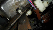
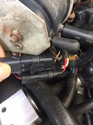
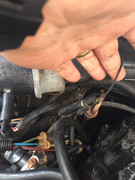
[FONT="]a) There is a "servo" mechanism under the hood that has 5 wires going to it as well as two vacuum connections. Three of these wires are used to operate the 2 valves (the orange wire is ground for both valves, the white wire operates the valve that lets air into the system, the red wire operates the valve that lets vacuum into the system). There is also a brown wire and a black wire. Note that on the Servo side, the wire is black but on the wire loom side, it is gray. These two wires connect to a variable resistor placed at the front of servo. This resistor is mounted on a wheel that connects to the wire that pulls your throttle open. What this effectively does is it allows the cruise control module to measure the position of your throttle. As the throttle opens, the resistance goes up. As it closes, the resistance goes down. For the vacuum connections, one vacuum connection is small and the other is larger. The small one comes from the vacuum canister under the bumper and provides vacuum for the servo. The large one connects to a small valve on the brake light switch above your brake pedal and is designed to quickly release vacuum from the system. Last, if you trace the wire loom under the hood back towards the firewall you will see that there is also a small black wire that connects through a weather proof connection to a lead that is mounted on the engine block to provide ground for the entire system.[/FONT]
[FONT="]b) There is a "special" brake light switch that not only has electrical connections, it also has this vacuum hose attached to it. The reason for this is that the moment you touch the brakes, the vacuum is released from the servo mechanism to quickly return the throttle position to idle.[/FONT]
[FONT="]c) There is a control module that sits under the dash and is mounted with two screws to the lower dash cover[/FONT]
[FONT="]d) There is the control switch mounted on the turn signal. This switch has 4 wires but only 3 of them connect to the control module. The 4th wire is connected to +12V power through a small 4AMP fuse you should find hanging near your fuse box or tucked behind the drivers kick plate. When the switch is turned on, it provides a 12V signal (from this fuse) to the brown wire on the control module. When you press the "hold" button, it provides a 12V signal to the green wire on the control module. When you slide the button to the "Resume" position, it will provide 12V power to the yellow wire on the control module.[/FONT]
[FONT="]e) There is a round module inside the firewall connected to your speedo cable just up and to the left of the throttle pedal. This module screws into the speedo cable coming from the transmission and then connects the other side through a short cable to the speedo. There are two wires coming out of this module that provide 8 pulses per rotation. The control module uses this to figure out what your current speed is.[/FONT]
[FONT="]Issues to look for ("how to fix" for each is listed below):[/FONT]
[FONT="]1) The control switch can go bad but it is easy to check[/FONT]
[FONT="]2) The vacuum can have a leak[/FONT]
[FONT="]3) The connector used to connect the cruise module to the Servo (under the hood) is flat out the WRONG type of connector for this. It is exposed to the elements and the connections will degrade over time. No amount of cleaning will give you a perfect connection[/FONT]
[FONT="]4) There is a fuse in the system that can blow[/FONT]
[FONT="]5) The connector that goes into the control module can suffer from bent pins[/FONT]
[FONT="]6) You could have a bad ground[/FONT]
[FONT="]Testing and "how to fix"[/FONT]
[FONT="]Tools you will need:[/FONT]
[FONT="] - a multi-meter than can measure voltage and resistance[/FONT]
[FONT="] - a phillips (star) screw driver[/FONT]
[FONT="] - a small flat screw driver[/FONT]
[FONT="] - (to test the vacuum ports) a vacuum bleeder tool like this one: https://www.summitracing.com/parts/lil-75000[/FONT]
[FONT="] - (optional) a 12V power supply - you can use the battery for this by adding a couple of wires if necessary[/FONT]
[FONT="]Testing and repair:[/FONT]
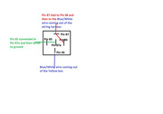
[FONT="]1) Control Switch and 4 AMP fuse - This is actually pretty easy to test. First, turn the button on the stalk to the "off" position. Next, what I did was to unscrew the control module from the bottom of the dash, use the small flat screw driver to compress the tabs on the case and then remove the top cover. This is important because there is a black plastic attachment (that will probably fall off) that has a ridge on it to keep the connector in place. If you try to just pull the cable off, this ridge will "over compress" the contacts which will then require you to spend time bending them back into position. Once you have the top off, you can drop the bottom of the case off and safely pull the control module free from the cable. With the cable section in your hand you should first check the ground. You can do this by setting your meter to “Resistance”, place the black probe on the black wire of the connector and place the red probe on a piece of metal (like one of the screws that holds your trim in place). You should measure close to 0 ohms. If not, the ground wire under the hood (the single Black wire that comes out of the loom for the Servo) is disconnected somewhere so look for a loose wire next to the ground lug behind the dipstick. If the ground is good, set your multi-meter for "DC volts" and hold the black probe on the black wire connector again. Next, turn the button on your stalk to the "on" position and place your red probe on the dark brown wire. It should read 12V. If not, have someone try to wiggle the switch while you hold the probes in place. If it holds a solid 12V, it means that the 4AMP fuse is perfect and that the "on" portion of the button is working. If wiggling the switch causes fluctuations in voltage, you have a bad switch. If you don't get any voltage at all, check the 4AMP fuse. Next, have someone press the "SET" button on the stalk while you move the probe to the green wire. While the button is depressed, the green wire should measure 12V. Next have your assistant slide the button to the "RESUME" position while you measure the Yellow wire. It should also read 12V when in this position. If you get a 12V signal with every test and the Brown wire is stable (doesn't drop to 0 volts while you wiggle the switch), your switch assembly is working properly. If you have any issues, you either have a bad switch or a blown fuse.[/FONT]
[FONT="]2) Next, confirm that the Brake light switch is passing a signal. To do this, place your black probe back on the Black wire and place the red probe on the Blue wire that has a White stripe. When you press the brake pedal, this signal should go to 12V. When the brake is released it should drop to 0V. At this point you should change your multi-meter to the "Resistance setting" and measure the resistance between the black and the blue/white wire. It should read close to 0 ohms. If not check to ensure you don't have LED bulbs installed in the rear.[/FONT]
[FONT="]3) While you have that cable free, you can also do a quick test of the Servo. To do this, change your multi-meter to "resistance" and place your black probe on the Orange wire connection and the red probe on the White wire. You should read between 40-50 ohms. Do the same with the Orange wire and the Red wire which should also read 40-50 ohms. If both read correctly, it means that the two valves in the Servo are probably ok (more testing of these later). You should also measure the variable resistor to make sure it is properly connected. To do this, place your black probe on the Gray wire and your red probe on the Tan wire. You should measure something near 580 ohms. This number doesn't have to be exact, you simply want something higher than 400 ohms and less than 1,000 ohms. I add this because there is a service document floating around on the web that says this measurement should be 2,000 Ohms which is incorrect for this model.[/FONT]
[FONT="]4) Testing the Servo. All tests are run with the engine off. The fastest and easiest way I have found to test the Servo is to start by cutting off the old harness and replacing it with proper Weather Pack Connectors like these:[/FONT]
[FONT="]https://www.summitracing.com/parts/aaf-all76267[/FONT]
[FONT="]https://www.summitracing.com/parts/aaf-all76266[/FONT]
[FONT="]The reality is that the existing connector is problematic. Mine had degraded to the point that I had 100K ohm resistance on 2 wires where I should have had 0 ohms. Even if you clean them, the environment in this area will cause them to corrode again. I recommend breaking this into two connectors simply for space reasons. The existing wires are quite short so it helps to use be able to stack them up. If you choose this route, I recommend tying the Black (connects to the gray wire on the loom side) and the Tan wires together since they are used for the same function (variable resistor) and then using the 3 wire solution to connect the Orange, White and Red wires.[/FONT]
[FONT="]To test this system the easiest way I found was after cutting the connector out, strip a small bit of insulation off each wire (to prep it for the new connectors) and twist the White and Red wires together on the servo side. Next, run a wire from the ground side of your battery to the Orange wire on the servo and then run a wire from the positive side of the battery to the White/Red wires you connected together. At this point you should see the throttle open to the WOT position as the servo activates. If it does not open the throttle, either the servo is bad or you don’t have enough vacuum or the vacuum is being released by the brake pedal switch. The system should hold vacuum for a couple of days so if it the throttle doesn’t open, try pulling the small vacuum fitting off. If you have vacuum, you will hear it hissing. If not, you need to trace the vacuum back to the vacuum canister behind the bumper to find the leak. Note, once you pull that small vacuum connector off, all vacuum will be released so you may need to start the vehicle to recharge the vacuum. If you do hear a hiss, it means the vacuum side is good so you may need to purchase the vacuum tester I recommend above to test the brake switch. What I did was to pull the larger vacuum connector off and insert my vacuum tester into the hose (not the servo, the hose!) and try to apply vacuum to it. If it holds vacuum it means that the brake valve is working properly. In this case, you can have your assistant touch the brake pedal which should release the vacuum. If not, the switch may need to be pushed in further into its mount to stop the leak. In an absolute worst case, you may have to replace the brake switch.[/FONT]
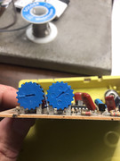
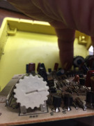
[FONT="]Last, none of the dials should need to be touched but if you touched them by mistake, a good starting point to reset them would look something like the ones in the picture below. For reference, the blue dial on the left is the "centering adjustment". If you press the "set" button at 30mph and the cruise control sets the speed to 33mph, you turn this dial to the left about 1/16". Similarly, if the speed drops to 27mph, you turn it 1/16" to the right. The blue dial on the right sets the "limit for the low speed". If you press the button at 30mph and it won't work but when you try at 35mph it works, simply back this dial off a bit. The factory setting was for 30mph and it is a good practice to aim for this with your adjustment. Last, the white dial is for "sensitivity". This basically sets how aggressively the cruise control will act. If you find that it surges a little too much when using cruise to climb a hill, back it off to the left a bit. If you want it to be more aggressive, turn it in small amounts to the right until it meets your needs[/FONT]
[FONT="] [/FONT]
[FONT="]
[/FONT]
[FONT="]HTH[/FONT]
[FONT="]Todd[/FONT]
[FONT="]Important note:[/FONT]
[FONT="]The cruise control in these vehicles will NOT work if you have changed your brake lights to LED. You can make it work by installing a relay but without the relay, the cruise control module will not receive the reference ground it needs to properly set the cruise mode. The reason for this is that with a normal "filament" style bulb, a multimeter will read measure +12V when the brakes are applied but when they are not, the filament acts as a piece of wire and the cruise control sees it as a ground. It uses this ground reference to set the speed properly. With an LED bulb, the cruise control sees an open circuit. This confuses the controller and makes it impossible to properly set the speed control. This one took me a while to figure out but the symptoms of this are that when you try to set the speed, the vehicle may surge multiple times before the cruise control gives up and shuts off. Send me a PM if you need to know how to install a relay so that you can use LED bulbs.[/FONT]
[FONT="]Key components of the system[/FONT]
[FONT="]a) There is a "servo" mechanism under the hood that has 5 wires going to it as well as two vacuum connections. Three of these wires are used to operate the 2 valves (the orange wire is ground for both valves, the white wire operates the valve that lets air into the system, the red wire operates the valve that lets vacuum into the system). There is also a brown wire and a black wire. Note that on the Servo side, the wire is black but on the wire loom side, it is gray. These two wires connect to a variable resistor placed at the front of servo. This resistor is mounted on a wheel that connects to the wire that pulls your throttle open. What this effectively does is it allows the cruise control module to measure the position of your throttle. As the throttle opens, the resistance goes up. As it closes, the resistance goes down. For the vacuum connections, one vacuum connection is small and the other is larger. The small one comes from the vacuum canister under the bumper and provides vacuum for the servo. The large one connects to a small valve on the brake light switch above your brake pedal and is designed to quickly release vacuum from the system. Last, if you trace the wire loom under the hood back towards the firewall you will see that there is also a small black wire that connects through a weather proof connection to a lead that is mounted on the engine block to provide ground for the entire system.[/FONT]
[FONT="]b) There is a "special" brake light switch that not only has electrical connections, it also has this vacuum hose attached to it. The reason for this is that the moment you touch the brakes, the vacuum is released from the servo mechanism to quickly return the throttle position to idle.[/FONT]
[FONT="]c) There is a control module that sits under the dash and is mounted with two screws to the lower dash cover[/FONT]
[FONT="]d) There is the control switch mounted on the turn signal. This switch has 4 wires but only 3 of them connect to the control module. The 4th wire is connected to +12V power through a small 4AMP fuse you should find hanging near your fuse box or tucked behind the drivers kick plate. When the switch is turned on, it provides a 12V signal (from this fuse) to the brown wire on the control module. When you press the "hold" button, it provides a 12V signal to the green wire on the control module. When you slide the button to the "Resume" position, it will provide 12V power to the yellow wire on the control module.[/FONT]
[FONT="]e) There is a round module inside the firewall connected to your speedo cable just up and to the left of the throttle pedal. This module screws into the speedo cable coming from the transmission and then connects the other side through a short cable to the speedo. There are two wires coming out of this module that provide 8 pulses per rotation. The control module uses this to figure out what your current speed is.[/FONT]
[FONT="]Issues to look for ("how to fix" for each is listed below):[/FONT]
[FONT="]1) The control switch can go bad but it is easy to check[/FONT]
[FONT="]2) The vacuum can have a leak[/FONT]
[FONT="]3) The connector used to connect the cruise module to the Servo (under the hood) is flat out the WRONG type of connector for this. It is exposed to the elements and the connections will degrade over time. No amount of cleaning will give you a perfect connection[/FONT]
[FONT="]4) There is a fuse in the system that can blow[/FONT]
[FONT="]5) The connector that goes into the control module can suffer from bent pins[/FONT]
[FONT="]6) You could have a bad ground[/FONT]
[FONT="]Testing and "how to fix"[/FONT]
[FONT="]Tools you will need:[/FONT]
[FONT="] - a multi-meter than can measure voltage and resistance[/FONT]
[FONT="] - a phillips (star) screw driver[/FONT]
[FONT="] - a small flat screw driver[/FONT]
[FONT="] - (to test the vacuum ports) a vacuum bleeder tool like this one: https://www.summitracing.com/parts/lil-75000[/FONT]
[FONT="] - (optional) a 12V power supply - you can use the battery for this by adding a couple of wires if necessary[/FONT]
[FONT="]Testing and repair:[/FONT]
[FONT="]1) Control Switch and 4 AMP fuse - This is actually pretty easy to test. First, turn the button on the stalk to the "off" position. Next, what I did was to unscrew the control module from the bottom of the dash, use the small flat screw driver to compress the tabs on the case and then remove the top cover. This is important because there is a black plastic attachment (that will probably fall off) that has a ridge on it to keep the connector in place. If you try to just pull the cable off, this ridge will "over compress" the contacts which will then require you to spend time bending them back into position. Once you have the top off, you can drop the bottom of the case off and safely pull the control module free from the cable. With the cable section in your hand you should first check the ground. You can do this by setting your meter to “Resistance”, place the black probe on the black wire of the connector and place the red probe on a piece of metal (like one of the screws that holds your trim in place). You should measure close to 0 ohms. If not, the ground wire under the hood (the single Black wire that comes out of the loom for the Servo) is disconnected somewhere so look for a loose wire next to the ground lug behind the dipstick. If the ground is good, set your multi-meter for "DC volts" and hold the black probe on the black wire connector again. Next, turn the button on your stalk to the "on" position and place your red probe on the dark brown wire. It should read 12V. If not, have someone try to wiggle the switch while you hold the probes in place. If it holds a solid 12V, it means that the 4AMP fuse is perfect and that the "on" portion of the button is working. If wiggling the switch causes fluctuations in voltage, you have a bad switch. If you don't get any voltage at all, check the 4AMP fuse. Next, have someone press the "SET" button on the stalk while you move the probe to the green wire. While the button is depressed, the green wire should measure 12V. Next have your assistant slide the button to the "RESUME" position while you measure the Yellow wire. It should also read 12V when in this position. If you get a 12V signal with every test and the Brown wire is stable (doesn't drop to 0 volts while you wiggle the switch), your switch assembly is working properly. If you have any issues, you either have a bad switch or a blown fuse.[/FONT]
[FONT="]2) Next, confirm that the Brake light switch is passing a signal. To do this, place your black probe back on the Black wire and place the red probe on the Blue wire that has a White stripe. When you press the brake pedal, this signal should go to 12V. When the brake is released it should drop to 0V. At this point you should change your multi-meter to the "Resistance setting" and measure the resistance between the black and the blue/white wire. It should read close to 0 ohms. If not check to ensure you don't have LED bulbs installed in the rear.[/FONT]
[FONT="]3) While you have that cable free, you can also do a quick test of the Servo. To do this, change your multi-meter to "resistance" and place your black probe on the Orange wire connection and the red probe on the White wire. You should read between 40-50 ohms. Do the same with the Orange wire and the Red wire which should also read 40-50 ohms. If both read correctly, it means that the two valves in the Servo are probably ok (more testing of these later). You should also measure the variable resistor to make sure it is properly connected. To do this, place your black probe on the Gray wire and your red probe on the Tan wire. You should measure something near 580 ohms. This number doesn't have to be exact, you simply want something higher than 400 ohms and less than 1,000 ohms. I add this because there is a service document floating around on the web that says this measurement should be 2,000 Ohms which is incorrect for this model.[/FONT]
[FONT="]4) Testing the Servo. All tests are run with the engine off. The fastest and easiest way I have found to test the Servo is to start by cutting off the old harness and replacing it with proper Weather Pack Connectors like these:[/FONT]
[FONT="]https://www.summitracing.com/parts/aaf-all76267[/FONT]
[FONT="]https://www.summitracing.com/parts/aaf-all76266[/FONT]
[FONT="]The reality is that the existing connector is problematic. Mine had degraded to the point that I had 100K ohm resistance on 2 wires where I should have had 0 ohms. Even if you clean them, the environment in this area will cause them to corrode again. I recommend breaking this into two connectors simply for space reasons. The existing wires are quite short so it helps to use be able to stack them up. If you choose this route, I recommend tying the Black (connects to the gray wire on the loom side) and the Tan wires together since they are used for the same function (variable resistor) and then using the 3 wire solution to connect the Orange, White and Red wires.[/FONT]
[FONT="]To test this system the easiest way I found was after cutting the connector out, strip a small bit of insulation off each wire (to prep it for the new connectors) and twist the White and Red wires together on the servo side. Next, run a wire from the ground side of your battery to the Orange wire on the servo and then run a wire from the positive side of the battery to the White/Red wires you connected together. At this point you should see the throttle open to the WOT position as the servo activates. If it does not open the throttle, either the servo is bad or you don’t have enough vacuum or the vacuum is being released by the brake pedal switch. The system should hold vacuum for a couple of days so if it the throttle doesn’t open, try pulling the small vacuum fitting off. If you have vacuum, you will hear it hissing. If not, you need to trace the vacuum back to the vacuum canister behind the bumper to find the leak. Note, once you pull that small vacuum connector off, all vacuum will be released so you may need to start the vehicle to recharge the vacuum. If you do hear a hiss, it means the vacuum side is good so you may need to purchase the vacuum tester I recommend above to test the brake switch. What I did was to pull the larger vacuum connector off and insert my vacuum tester into the hose (not the servo, the hose!) and try to apply vacuum to it. If it holds vacuum it means that the brake valve is working properly. In this case, you can have your assistant touch the brake pedal which should release the vacuum. If not, the switch may need to be pushed in further into its mount to stop the leak. In an absolute worst case, you may have to replace the brake switch.[/FONT]
[FONT="]Last, none of the dials should need to be touched but if you touched them by mistake, a good starting point to reset them would look something like the ones in the picture below. For reference, the blue dial on the left is the "centering adjustment". If you press the "set" button at 30mph and the cruise control sets the speed to 33mph, you turn this dial to the left about 1/16". Similarly, if the speed drops to 27mph, you turn it 1/16" to the right. The blue dial on the right sets the "limit for the low speed". If you press the button at 30mph and it won't work but when you try at 35mph it works, simply back this dial off a bit. The factory setting was for 30mph and it is a good practice to aim for this with your adjustment. Last, the white dial is for "sensitivity". This basically sets how aggressively the cruise control will act. If you find that it surges a little too much when using cruise to climb a hill, back it off to the left a bit. If you want it to be more aggressive, turn it in small amounts to the right until it meets your needs[/FONT]
[FONT="]
[/FONT][FONT="]
[/FONT]
[FONT="]HTH[/FONT]
[FONT="]Todd[/FONT]
Last edited: