00BlackClassic
NAXJA Forum User
- Location
- Lubbock
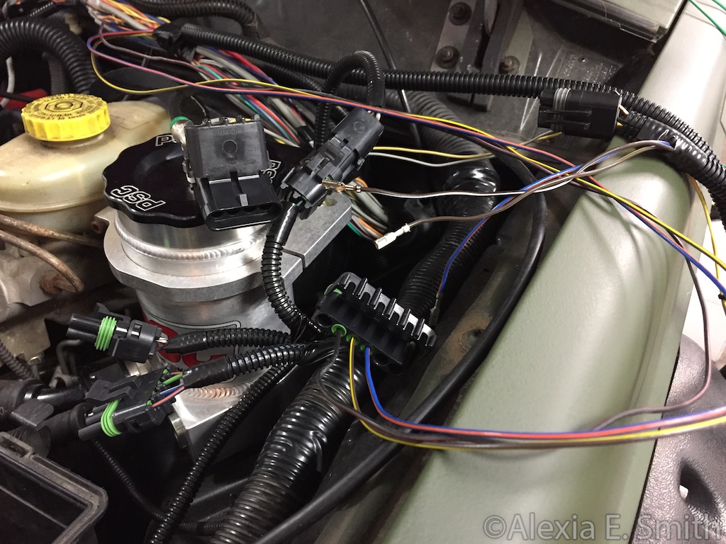
Which coil pack is that?
Which coil pack is that?
What year is the jeep? Did you have a coil rail previously or a distributor?
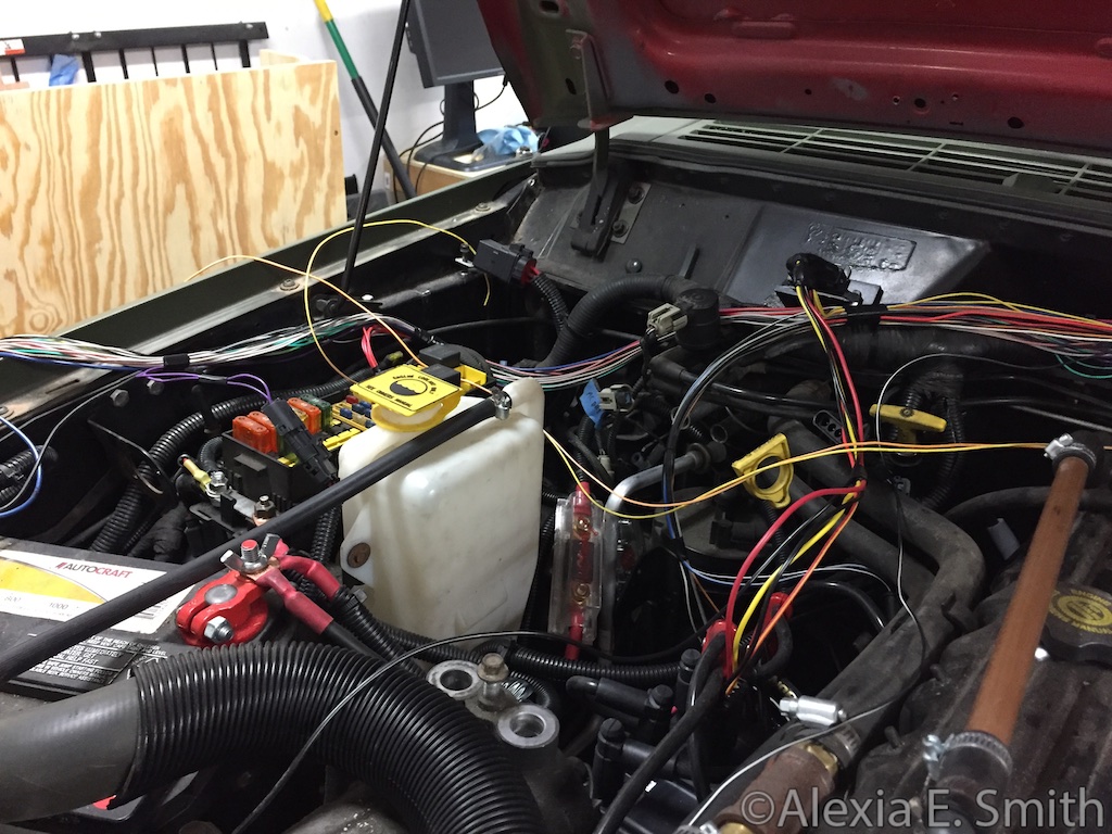
 Still have not finished the setup.
I opened the garage door and I could smell that the magic smoke escaped from the Haltech ECU from five feet away.
Ugh oh, what happened?
I barbecued the ECU. I am getting a heavily discounted replacement though. :|
I barbecued the ECU. I am getting a heavily discounted replacement though. :|
How did you BBQ it? wiring fault? :explosion
Any updates?