• Welcome to the new NAXJA Forum! If your password does not work, please use "Forgot your password?" link on the log-in page. Please feel free to reach out to [email protected] if we can provide any assistance.

GM Drive-by-Wire Throttle Body and a Haltech ECU

Alexia

NAXJA Forum User
Location
Huntsville, AL
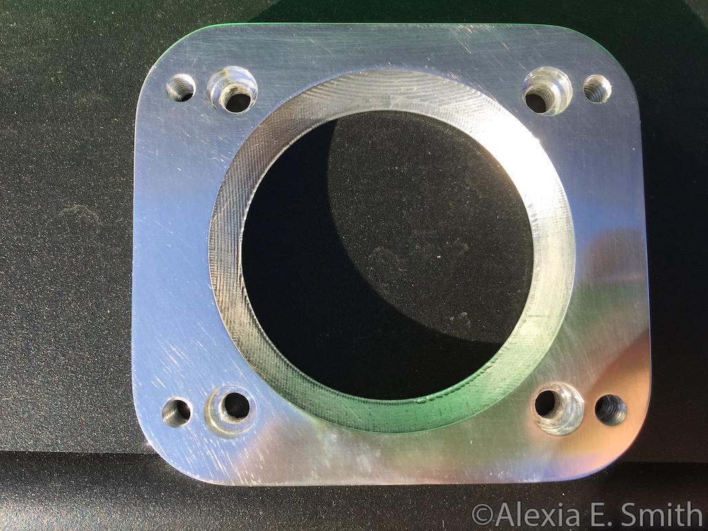
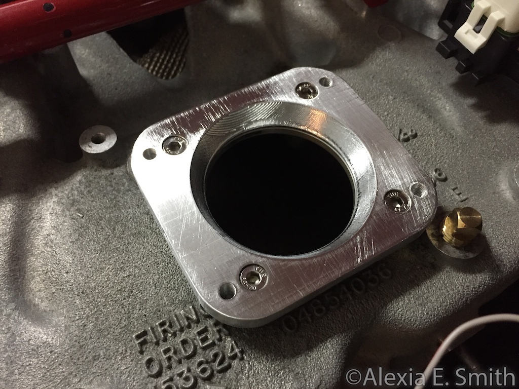
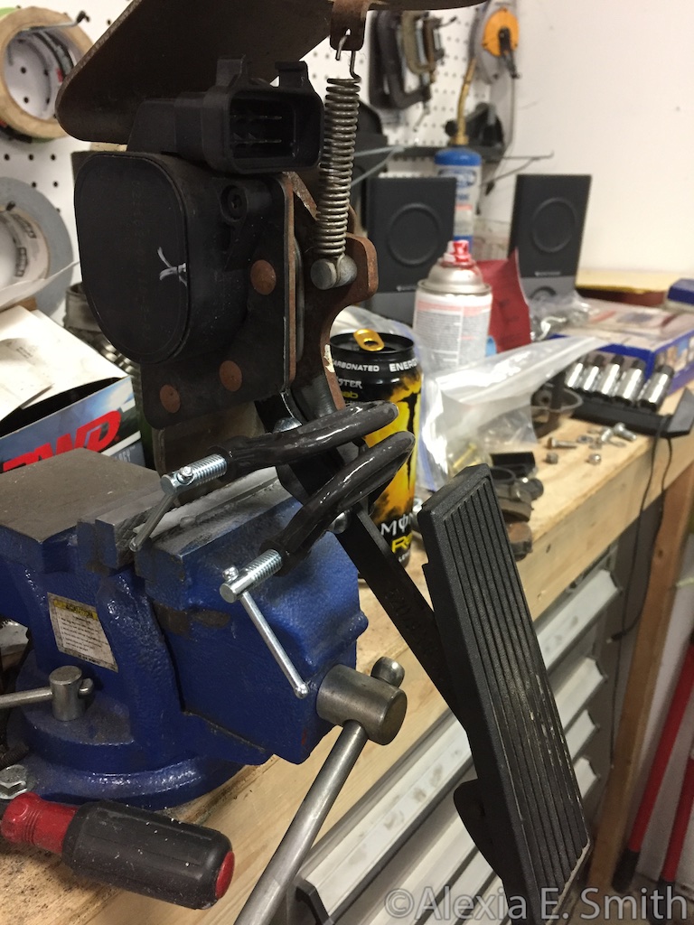
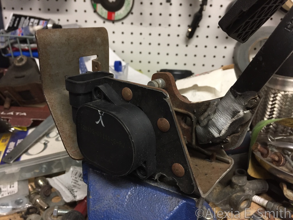
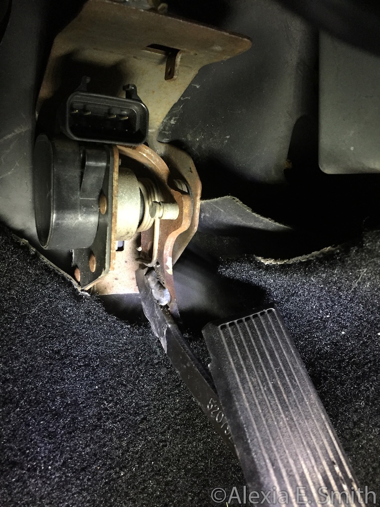
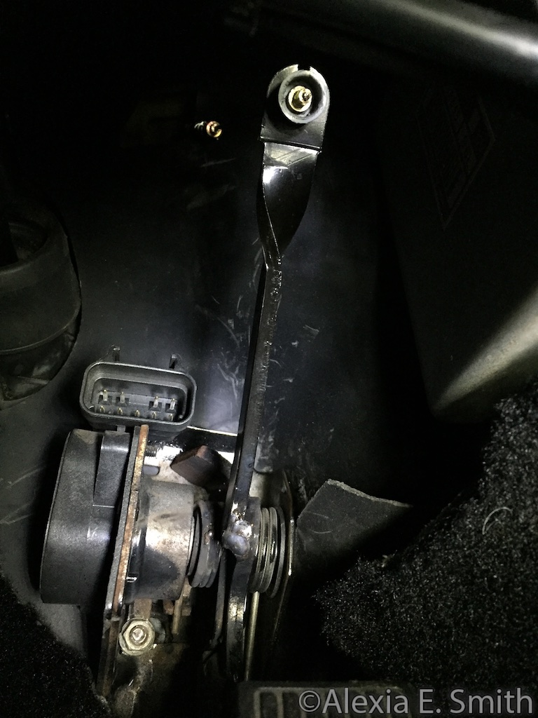
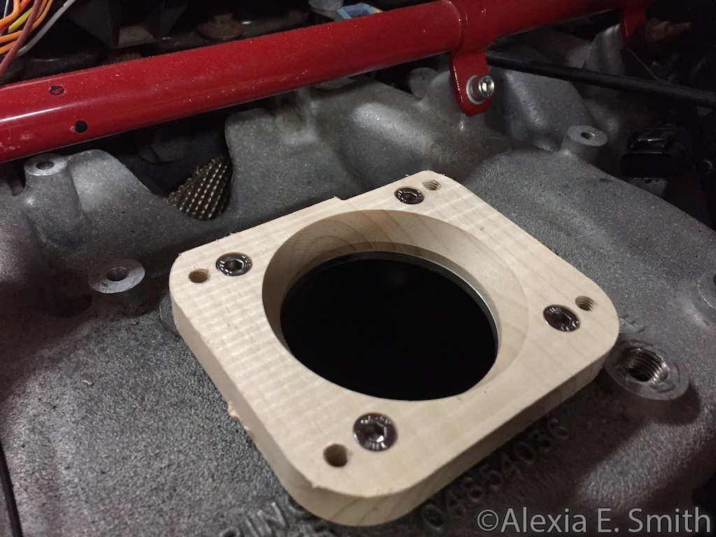
I started to install a Haltech ECU so I could do actual tuning instead of screwing around with useless JTEC PCM tuning. Since the Haltech supports drive-by-wire(DBW) I decided to try fitting a GM DBW throttle body on a stock manifold.

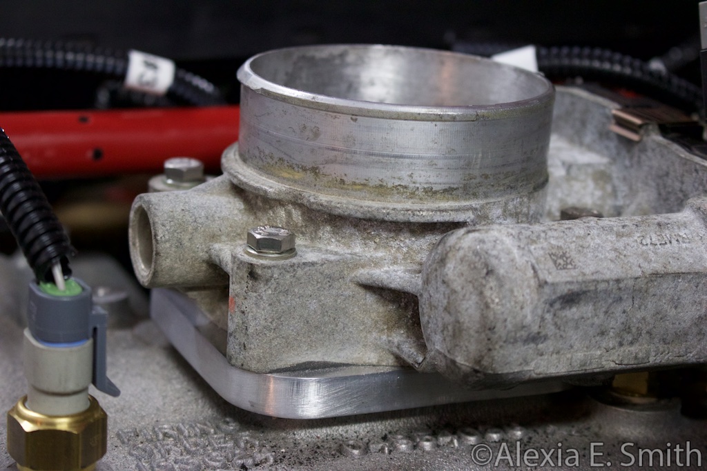
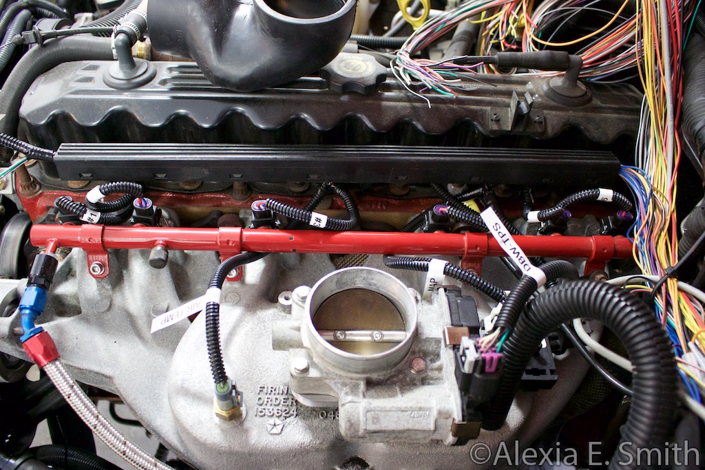
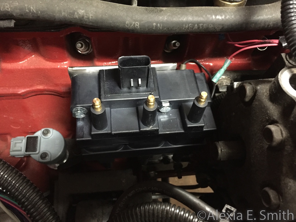
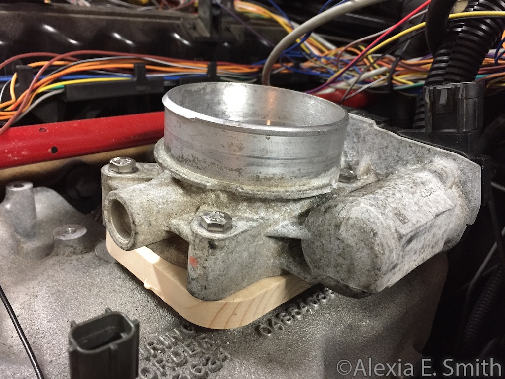
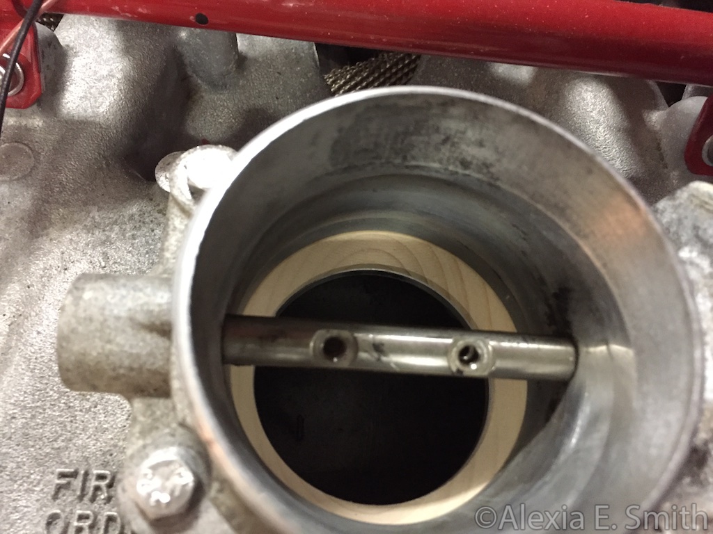
The only draw back so far is that I will have to relocate the valve cover vacuum line to a spare port on the side of the intake manifold. All the other rotations resulted in much worse fitment problems.

gallery_1_12_140124.png


gallery_1_12_220825.jpg


gallery_1_12_45051.jpg


gallery_1_12_210094.jpg
 
But it wasn't necessary to use a dbw tb to run the haltech?

Correct, it is not required. It just makes it easier to get the best possible engine tune since the ECU will be controlling every aspect of the engine instead of playing constant catch up to a mechanical throttle.
 
One of the optocouplers for the Z-axis on the motion controller card broke a solder joint from vibration. Result: The end mill slamming into the work piece since the Z-axis would only move downwards even when commanded to move upwards. :| I fixed the solder joint, but the Z-axis is losing up to 7mm of accuracy. I will probably have to put a socket on the circuit board and run wires to fix it.
 
I repaired the Z-axis late last week, but there a few other set backs with getting parts shipped that I am waiting on. I was sent the wrong countersinking bits wasting a whole week on shipping. So I have made orders for other countersinking bits that should arrive tomorrow, Saturday, and Monday. Hopefully at least one of them is remotely correct.
 
The end mill snapped in half during the final cut out of the piece so I ended up having to some manual cutting and sanding to finish the piece.

IMG_2135.jpg


This was before more sanding and polishing.
IMG_2133.jpg


IMG_0816.jpg


Progress on the wiring harness. I need to get some wire tie downs to utilize in the now empty bolt holes from the throttle linkage bracket.
IMG_0815.jpg
 
I wrapped up the GM accelerator position pedal(APP) modifications tonight. There is one more I might do that involves the transmission kick down cable, but I have to see what I am doing with the transmission programming first.

The pedal position is amazing now since I could customize it anywhere I wished it to be.

IMG_2141.jpg


IMG_2143.jpg


IMG_2142.jpg
 
Out of curiosity what are your plans for the TV cable that runs down to the trans? Also are you going to keep the stock TCM or build your own TCM?

I am going to hook the "kick down" cable from the transmission to the top of the pedal using the rest of the stock pedal. I am out of wire rope crimps so I am waiting for those to arrive. The TV cable is only a few inches short so I cut the length off the throttle cable and I will crimp it on the end while utilizing the stock throttle pedal connector. All that arrives next week due to the holiday.

As for the TCM I should only need to feed it a TPS signal. However, I have been tinkering with building my own TCM which I will probably mess with more next year after getting it all running.

intriguing. does haltech make an adapter for JTEC harnesses or did you have to repin the ecu connector?

There is no adapter and repinning is possible, but I felt it would be easier for my particular setup to go fully custom.
 
I am going to hook the "kick down" cable from the transmission to the top of the pedal using the rest of the stock pedal. I am out of wire rope crimps so I am waiting for those to arrive. The TV cable is only a few inches short so I cut the length off the throttle cable and I will crimp it on the end while utilizing the stock throttle pedal connector. All that arrives next week due to the holiday.

As for the TCM I should only need to feed it a TPS signal. However, I have been tinkering with building my own TCM which I will probably mess with more next year after getting it all running.


There is no adapter and repinning is possible, but I felt it would be easier for my particular setup to go fully custom.
out of curiosity what was your main motivation to install the haltech? are you running a stroker/boost? definitely keep us posted/take as many pics as possible. I'd definitely consider doing this down the road if I end up going stroker in the next year or two.
 
out of curiosity what was your main motivation to install the haltech? are you running a stroker/boost? definitely keep us posted/take as many pics as possible. I'd definitely consider doing this down the road if I end up going stroker in the next year or two.

The AEM FIC was not working out for me with boost being added. Nor was it working well with no boost. So the Haltech is going in to be a complete replacement solution.
 
It's nice to see a company that seems to actually support their product well. I'll keep an eye on this.

Haltech wins for me. I sent them an email asking, "Hey, can I get your CAN bus protocol specification?" Within twenty-four hours I had a complete documentation set, for free, with no strings attached.
 
The accelerator position pedal is finished. The hole in the firewall had to be enlarged, but afterwards the other modifications to the transmission valve cable worked out great. Hooking the TVC up to the pedal is a little silly, but it saves a lot of engineering of a CAN bus device to actuate a solenoid on the transmission.

IMG_2146.jpg


IMG_2147.jpg
 
After a long break I have tackled mounting the coil pack. There is enough room to get to the spark plugs and install wires. I am in between coats of paint right now while I make this post.

IMG_2156.jpg


IMG_2157.jpg
 
Back
Top