how to wire a relay for lights... the 'RIGHT' way

lost track of how many times I have posted this pic. I ALWAYS do neg tripped relays when ever I need any switches wired up. I have melted to many GOOD/PROPER sized switches running power through them, yes it happens even with the correct wiring and fuse set up. Most switches are not meant to carry the amp load for a continued amount of time, no matter what is printed on them.

When you have a switch that melts and starts a fire you will understand, but until then keep doing what y'all want. Me I will always wire neg trip relays. I have had one small fire that I thankfully caught and melted a few switches as well. And YES these where set up the correct way for a positive trip relay and where NOT overloaded by any means. Amps is what causes the heat so keep that in mind as well.

As far as a short goes..in a relay style setup from the switch side... If you short a positive wire to ground you get what? Yup you guessed it you burn crap. Basically make yourself a little welder. Try this test. Take a length of wire and hook one side up to the pos side of a battery charger and the other to the neg side of the battery charger. Now turn it on for just a sec or two and see what happens to that wire. I bet the wires insulation goes up in smoke or gets very hot. That's how fast the amperage can destroy a wire when under load. When you short a ground what do you get? Yup the accessory turns on but no welder like action, and no wire going up in smoke to potentially case a fire and or loose of the vehicle.

The negative vs. positive trip relay argument is as old as the Chevy vs. Ford debate. So no one will win as we all agree we feel our own way is better because we have had no issues with the way we do it now so why change. But that's OK each to there own.

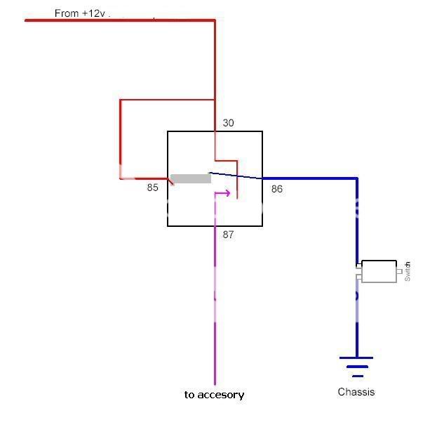
OK Ok OK now for that pic might be easier to follow then the OP's paint doctored pic... simple and to the point

Oh even though it is not in the pic never forget to use the correct size fuse on the +12v source before the relay
relay2.jpg
 
Also when switching the ground for a relay the power will/can actually back feed through the coil when the ground switch is open. Not really a big deal for a simple circuit like you have drawn up, but can cause complications when doing more intricate circuits. Their are relays available with built in diodes to prevent this though.

There's more than one way to skin a cat.... errr, I mean wire a circuit

This is true to. Alot of the relays will have a diode in them and I have even used some relay harnesses that have a diode built into them as well.
 
Sorry, but a switch or wire (whether on the positive or negative side of the circuit) that melts or catches on fire was either not properly wired, not properly sized or not properly fused.

Having said that, I personally could care less what technique anyone uses. Some circuits are better negatively switched and some circuits are better positively switched and ideally, we would all know which to do when. What I am absolutely sure of is that Abita makes a helluva beer and it's about time for one.
 
Any one have any real pictures :o

I'm going to be doing some work this weekend, and I've already got two rock lights mounted and wires running from them, and switches in my dash, but no relays. Do I just pick up relays from Autozone or something, and which ones if so?
 
Honestly, trying to depict wiring lay out in a real picture is a pain in the ass. Better to go off schematics. Ask for bosch style relays (however they may not know what you're talking about), they come in 4 and 5 pin layouts, either one will work.

note: pictured is the 5 pin style, terminal 87a has power supplied from terminal 30 when the relay is not energized (or "off"), terminal 87 is supplied power when the relay is energized (or "on") from terminal 30, subsequently terminal 87a turns "off". Terminals 85 and 86 control the relay, one goes to power, the other gets grounded.
0332209150.jpg
 
Last edited:
I can appreciate the effort ericfx1984, but why try to rewrite the book on relay wiring with a hastily thrown together description and a sloppy MS Paint drawing when there is so much good information already out there? Here's my favorite relay wiring site which includes lots of interactive diagrams, drawings, photos, and technical information that explains things so well that even a complete novice could follow along...

http://www.bcae1.com/relays.htm

very nice site!
 
Hmmm,

This stuff makes me crazy! :gonnablow I hate to lecture, but .... :lecture:
The most mis-understood thing I deal with is Automotive Basic Electrical Systems! Being a professional automotive/diesel/heavy equipment instructor, I am amazed at how much mis-information is out there. The previously mentioned site (http://www.bcae1.com/relays.htm) is a nice beginning, but there is additional information that will help folks get a better understanding.

Having recently spent five years running a major heavy equipment distributor's training program, I was amazed at how lacking the general understanding of basic electrical systems was, and therefore the large amount of "poking around in the dark" that masqueraded as "diagnostics".:dunno:

One of my golden rules is, "If you understand how it works, you can figure out how to fix it!' For this reason, you MUST understand the theory of how things work, before you can have a true understanding of how to fix them. Sure, you can just replace a part to fix something, but do you know why it needed to be replaced? And, more importantly is there something else going on that will cause a repeat failure? I guarantee that if you don't understand the system, these secondary issues will elude you.:eek:

Another one of my favorite sayings is, "If you pay peanuts, you'll get monkies!" :moon:Nuff said about all those shops out there that don't pay well. If they don't care enough to pay exceptional techs, and thereby attract the best, they'l get exactly what they pay for. A good examply would be Pep Boys versus a seasoned Mercedes Dealer Tech (a good dealer that is, not some schlep). Anyway, I think you get the point.:doh:

Well, back to basic electrical. Relays are electrical devices that allow a small amount of current to control a large(r) amount of current.

Up until 1991 for example, (believe it or not) Ford trucks did not have relays in the headlight circuit. This meant that all of the current that flowed through the bulb filaments, also had to flow through everything else in the circuit, including the headlight switch relatively far away, under the dash. For this reason the switch had to be a relatively heavy duty device with large contacts and a large frame capable of dissapating lots of heat. Anyone who did not understand relays and wired up trailer lights without them soon learned that blinking headlights, switch failures and melted wires would certainly follow.:repair:

By properly wiring relays into the circuit these issues were avoided, and in fact the stock system could be greatly improved by wiring relays into not only the trailer lights, but the original headlight circuit too. It's all about current flow and something we call "voltage drop".

When ever I hear someone say, "I ohmed out the wire" my spine crawls, as that is usually a clear signal that they really have no clue of how to properly diagnose electrical circuits.:laugh: An ohm meter CANNOT tell you the quality of a wire! Sure it can tell you if there are any shorts to power, ground or to other wires, but that's where the use of an ohm meter should stop! A volt meter is the proper testing device, but I do not have the space here to teach it's proper use.

Most manufacturers teach ohm meter use because the circuit has to be open (dead) when doing resistance checks, so there is less chance that neophyte techs will damage things due to unintended circuit overloads. They have to try to keep the systems safe from the pokers and stabbers, and working on open circuits is about the safest way to do it. The problem is that ohm meters can and will lie to you! But, voltmeters will ALWAYS show a true indication of what's going on when properly used on an energized circuit, especially those circuits that are not working properly. Like most other tools, knowing how to use them properly is the key, and that is a whole other issue that cannot be adequately explained here.

Okay, back to relays: When ever you have an inductive load (a coil of wire that becomes a magnet, like a relay coil) you need spike protection, which is the reason for the built-in diode, or what is commonly called a spike-protection diode. The reason for this is that when the coil (relay) is de-energized or turned off, the collapsing magnetic field self-induces a voltage spike. This spike seeks ground, as it is a voltage, so it does not want to go to "power" (B+) as that is obvoiusly an opposing voltage. The thing that most folks don't realize is that this spike is exponentially higher in voltage than the source voltage of 12 volts nominal. As part of my basic electrical classes we measure this spike, and depending on the relay used this spike will vary from a low of about 250-300 volts to over 4000!

This is why a spike protection diode is necessary! This high voltage spike will jump the contacts of the switch (if it is a ground-side switch) and eventually destroy the switch. If the "switch" is a driver transistor in a computer, the lack of spike protection makes short work of destroying the internal driver circuit. Many manufacturers have gone to power-side switching specifically for this reason, as having the ground side unswitched allows the spike to flow directly to battery ground, and the vehicle battery is the best condensor (spike protection device) we have in the vehicle. This is also the purpose for the condensor you find next to the breaker points in an "old-fashioned" distributor, for those old farts like me who remember working on them.

Use ISO (International Standards Organization) compliant relays: Bosch relays conform to the standards which specify the size, pin configuration, and case illustrations among other things. It doesn't pay to waste your money on the cheaper stuff!;)

So, in conclusion, if you are wiring up relays with ground-side switches, you need to understand how to properly wire up relays with spike protection diodes, or you will eventually wipe out the switch. Put the switch on the power side, with proper fusing, and that issue vanishes. In fact, speaking of proper fusing, this is what's behind the huge ongoing cruise control recall Ford has had on their vehicles for some years now. The hot wire for the hydraulic switch redundant cancellation/speed set prevention signal was not fused from the factory. When the connector on the switch corrodes and creates resistance the cruise system stops working. If left unattended, the resistance continues to build, as does the heat generated by this corrosion. When the circuit shorts, now because the circuit was not fused a direct short ocurrs and in some cases the vehicle experiences a "thermal event"!:flame:

So, I guess the moral of the story is, know your electrical systems, and more importantly know and understand how they work. Once you do, with schematic in hand, all the rest falls into place quite nicely.:cheers:


BTW: Trivia Question of the Day: Why do most better relays have an amp rating with two numbers listed such as: 30/40?

Enjoy! :D

ProfessorGT
 
Up until 1991 for example, (believe it or not) Ford trucks did not have relays in the headlight circuit. This meant that all of the current that flowed through the bulb filaments, also had to flow through everything else in the circuit, including the headlight switch relatively far away, under the dash. For this reason the switch had to be a relatively heavy duty device with large contacts and a large frame capable of dissapating lots of heat. Anyone who did not understand relays and wired up trailer lights without them soon learned that blinking headlights, switch failures and melted wires would certainly follow.:repair:

Wow, 1991? I don't believe it! How closely have you looked at the headlight wiring schematic for our beloved XJ's? All the way through the end of their production run...
 
BTW: Trivia Question of the Day: Why do most better relays have an amp rating with two numbers listed such as: 30/40?

How much it can open vs. how much it can close.

shawnhancel said:
What Ga wire should be used in what amp ratings.

:skull2:

To size a wire, you need to be a P.E...

To size a wire, you need the amperage & the length.
Always fuse your circuits. Always.

There's many different wire types, so generally stating that X size wire is good for X amps can cause problems.
If you're talking residential cabling, you use #12 for a 20A circuit, #14 for a 15A, and #10 for a 30A... but those are different solid conductors than what's used in cars.

Here's a table from the National Electric Code handbook, I've copied the 60 degree values, because they're a little more forgiving.
NEC table 310.17
Allowable ampacities of single insulated conductors rated 0-2000 volts in free air. Copper. 60*.
(types: RHW, THHW, THW, THWN, XHHW, ZW)

#14 = 25A
#12 = 30A
#10 = 40A
#8 = 60A
#6 = 80A
#4 = 105A
#3 = 120A
#2 = 140A
#1 = 165A

The length of your wire determines it's resistance. Resistance causes voltage drop. When voltage drops, amperage increases. Amperage burns fuses & wires. Electricity has a very simple calculation:
Amperage = Voltage / Resistance

NEC Table 9
Resistance per 1ft, copper, pvc conduit

#14 = .0027 ohms
#12 = .0017 ohms
#10 = .0011 ohms
#8 = .00069 ohms
#6 = .00044 ohms
#4 - .00029 ohms
#3 = .00023 ohms
#2 = .00019 ohms
_____________________________________________________________________________________
Example:
First things first, I would NOT put (2) 100w lights on #14 wire.

(2) loads, on #14 wire. 1 is 20', the other is 40'
The load is a pair of 100w lights on a 12v system.
Voltage = Amperage x Resistance
Amperage = 16.6A (2 100w lights @ 12v) (200/12 = 16.6)
Resistance = calculated per length

20 foot:
20 x .0027 = .054 ohms resistance
Voltage = Amperage x Resistance
Voltage = 16.6 x .054
Voltage = 0.89
So the voltage dropped on 16.6A on 20' of #14 is .89 OR
12v - .89 = 11.11 Volts

40 foot:
40 x .0027 = .108 ohms resistance
Voltage = Amperage x Resistance
Voltage = 16.6 x .108
Voltage = 1.79
So the voltage dropped on 16.6A on 40' of #14 is 1.79 OR
12v - 1.79 = 10.21 Volts

So, who cares?

Work the voltage drop back into the initial calculation, and compare the differences.

200w = lights
Amperage = Wattage / Voltage

20 foot:
Amperage = Wattage / Voltage
Amperage = 200w / 11.11V
Amperage = 18

40 foot:
Amperage = Wattage / Voltage
Amperage = 200w / 10.21
Amperage = 19.58

Tough to say one blanket statement that works for all cases.
It's not cost effective to blindly upsize your wire, but if you're unsure what you're doing, it never hurts to err on the larger wire size.
 
Where do you get your relays? I asked if they had them at autozone and the guy told me I had to tell him what vehicle it goes on to find one.
 
Where do you get your relays? I asked if they had them at autozone and the guy told me I had to tell him what vehicle it goes on to find one.

I tend to pick them up at Electronics Supply in KCMO

that or I get them from the bone yard... it is amazing how long a quality relay will last 20+ years...
 
Hmmm,

This stuff makes me crazy!.....

....AND WHAT PROCEEDED....

ProfessorGT

....MAGNIFICANTLY SAID :worship:

How much it can open vs. how much it can close.

...for it to operate within safe parameters

props for posting wire parameters as well....VEERRRY good info for people to understand....saw it, & got flashbacks of getting drilled with it at school :read:....crazy how little the E1's i work with dont (need to?) refer to it

Where do you get your relays? I asked if they had them at autozone and the guy told me I had to tell him what vehicle it goes on to find one.

HA! :confused1 ....part store monkeys (not you sledneck, the chimp that asked that)

should i throw another wrench into this wheel in motion??...i say continuous/constant duty solenoids!... i want to wire up an aux fuse box (following FitchVA's lead) for lights/compressor/inverter/etc, & ive brushing up on how to wire up an appropriate solenoid to amp things up (hehe)... too far off track for this thread?
 
Back
Top