Anyman's build

Well, I suppose it’s time to get some updates up. Funny episode here, a little while back I was FINALLY getting around to welding up the rear quarter panels from when I did my cut and fold. Anyway, I had shut the garage door because the sun was getting in my helmet making it impossible to see what I was doing. I was inspecting a weld when through a screw hole I noticed a flame flicker inside the fender! :wow:

So I frantically ran around the XJ and hit the garage door opener so I could open the lift gate. Then I realized that the fire was in between the fender and the inner panel. I tried to get some water in there but it wasn’t working so I resorted to snagging the extinguisher off the roll cage and spraying it up into the vents so that the chemicals could then fall down onto the fire. After I got the panel out of the way this is what I found:
8450533766_cb720acc36.jpg


8450533734_71ae7d6a82.jpg


What happened is some expandable foam I had used to seal up some pin holes had caught on fire. I was pretty surprised since I was welding sheet metal and therefore using very low heat. Not sure if a spark hit it or what, but that stuff is VERY flammable! :banghead:

Well, off to the JY to source a wiring harness for that rear panel. I try to keep running lists for places like Home Depot and the JY, so here’s what I hauled off with for $35:
8450533804_e0686a1f44.jpg


I tried to get the exact same connectors but failed so I had to splice one of my old ones in
8450533698_a5202127a3.jpg


In hindsight I should have spliced the other ends in closer so that they were in the fender area, but I left them long and spliced them in under the rear seat
8450533664_8b689ae732.jpg


8450533570_a5b2f7a63b.jpg


Luckily that was all there was too it, could have been worse! However, now when I turn the XJ off one of my rear speakers makes a buzzing noise for about 3 seconds. I have no idea what that is all about, the only thing I can think to do is figure out which wires are the speaker wires and replace the crimp connector with solder…
 
I’ve had my Spectre cowl air intake installed for about 8 months and I was getting ready to take a road trip so I figured I should clean it out. Really the only driving I’ve done with it installed is limited local driving, a long dirt road one afternoon and 5 days in Moab.

Removing the filter this is how it looked
8448778231_e5d31b2263_c.jpg


I was pretty surprised since I didn’t feel like I had driven the XJ that much. Some people claim this filter is too small for the XJ, others say it’s fine, I have no idea either way. I will say that one of my few trips was very dusty and then Moab always creates junk even though you may not see it… Anyway, I was happy to see how clean the inside of the filter was
8449862344_ee564a6bba_c.jpg


Looking into the intake tubing it was pretty much the same, here is the pre-filter side
8448777967_eb738b9310_c.jpg


And here it is post-filter
8449862674_46a17168c6_c.jpg


I was also surprised to see how much condensation accumulates in there… Well, I haven’t had any adverse effects yet.

The instructions read to lightly tap the filter on its side and use a soft brush to remove excess dirt and debris, which I did
8449862088_e4ed30ccec_c.jpg


Spectre makes a cleaning and oiling kit, but the local parts store stocks K&N, and I had some on hand from my previous setup, so I used it.
8449861738_f28f865294_c.jpg


I don’t know if I used WAY too much oil or what, but it was taking forever to dry, in the end I stuck a space heater on it to speed the process up some
8449861524_5e52f6f015_c.jpg


So that’s that. I put it back together and it’s running great. Of course the very next day on my trip we hit some VERY dusty conditions. It might be a good idea to pull it and see how dirty it got and then see how dirty it gets with daily driving over the next few months… we’ll see if I have time for that.
 
A little more travel log, but in the end it is pertinent ;)

So for the winter solstice I took my 3 older boys and we went on a trip with a local expedition club. Out in the desert near Wendover there are some tubes that are placed so as to line up with the winter and summer solstices. The group organizes a camping trip every winter to catch the sun rising in the tubes, which are called the “Sun Tunnels

Here we are making final preparations for the trip:
8449853398_24e4c17243_c.jpg


For some reason I didn’t snag any night shots, too cold I suppose! (It got down to 4°) Despite the fact that most people stayed up into the wee hours around the several fires we had going, in the morning there was a good group that braved the temps to try and get a good shot of the sun rise
8449853350_f3b9f88b78_c.jpg


Unfortunately there were some low-lying clouds which for the most part denied us the shot we wanted
8470300581_1063abab0b_c.jpg


The boys decided NOT to get up too early!
8449853300_5814859f91_c.jpg


I returned the next day with a group which traveled along the old transcontinental railway line. Despite having been abandoned close to 100 years ago the road along the old line is still flat with absolutely no washboard. We were able to run 60mph along it
8448767951_33a4d12ba0_c.jpg


Road trips are great because you can see some interesting stuff. I’ve been held up by herds of cows, sheep, deer and even a moose that refused to yield the road for about 10 minutes. This was my first run-in with a heard of horses though
8448767839_cab95d2ec5_c.jpg
 
While on the solstice trip, I noticed that I was still making contact with something up front when I would hit a bump at speed. :banghead: I thought I had addressed this issue by extending my shocks and shaving bolts down near my sway bar. When I returned home I removed the spings so I could raise the axle all the way up and realized that the track bar mount was making contact with the axle truss.
8356823776_dd40c43bc3_c.jpg


:puke:
Major bummer. I looked into buying a new mount but Rubicon Express is the only manufacturer that I can find who makes one with a brace. I figured rather than buy one and modify it I would just make my own – that way I can be sure to get it to fit exactly where I want it.

I started off by plating the driver’s side frame with 3/16” plate
8356823722_d1b95c8fea_c.jpg


8355760433_3eebaf60c3_c.jpg


8356823516_356a2e8638_c.jpg


8355760119_5d725ef59c_c.jpg


The bottom is already plated with what appears to be 1/8” but I figured it was not good enough so I added some stitch welding and then plated that as well.
8356823426_2930601292_c.jpg


8356823024_4287f2998c_c.jpg


8355759773_8091c7b65f_c.jpg


Looks like I missed a few pics here, but here the bottom is welded up and cleaned up and I’ve also cut a piece and fitted it into the angled part of the frame and filled that in:
8356822868_166f6ae70f_c.jpg
 
I don’t know why but this reminded me of that Mr Bill skit from the old SNL days :D
8355759991_b912b7bec6_c.jpg


So FINALLY I can get to making the actual track bar mount! I used some 1/4" angle to make it
8355764415_d7de183b1a_c.jpg


For some reason I can’t explain, at some point I got the idea that making this cross-section would add strength to my design… I’m not sure about that right now, but I do know this: is sure made it ugly! :rolleyes:
8355763889_b0d4bc99f1_c.jpg


8356826654_bd798421a9_c.jpg


Here it is tacked into place so that I could test clearances
8355762849_4aa0914c19_c.jpg


I wanted to push the mount out as far as possible to lengthen my track bar as much as possible. I think I gained about 2” of length, which is nice. The mount is as far outboard as it can be with my springs. Here I am testing as best I can in the garage
8356825576_f35d4cb566_c.jpg


8355761747_fa89b9c5e2_c.jpg


So I burned it all home and started final cleanup for paint
8356824514_bf7b37c71c_c.jpg


Took a quick break to get some metal out of my eye – it’s amazing how it can find a way around a face shield. It FEALT like I had a huge chunk in there, and this is all there was…
8355760905_6f8958e8b2_c.jpg


All painted – now it’s true that I suck at doing the prep work right and painting, but the temperature was also around 15° which wasn’t helping matters
8355759513_35df032737_c.jpg


:gee:

While I was setting everything up I paid close attention to my draglink and tie rod clearance. I have been wondering if they are making contact as well. Looks like they clear ... just barely. I’m not sure if I want to do something to address this in the future or not, we’ll see.
8355765271_ca46e2aec2_c.jpg
 
Bolting everything back up to go do a real flex test, the new track bar is about 2” shorter than my drag link. The angles aren't exact, but they are close and I’m happy :cool:
8356829636_29d8e82fb5_c.jpg


So, I took it to the local flex field and checked it out. With the vehicle settled and flexing I actually put the mount closer to the spring than I had thought. When I stuff driver’s side it makes slight contact with the spring. It’s really not an issue, just will require paint once in a while.
8355765727_164a8ed0b2_c.jpg


Some flex shots
8355765477_afe5fd37a4_c.jpg


8356829084_4f2d601825_c.jpg


8355766029_ca18f9f220_c.jpg


I tried to hit some hard bumps on my way out of the field – no banging from up front so far. Even though I haven’t re-installed my sway bar yet I’m very happy with the ride. The dead spot I had up front is gone now and the steering is much more responsive. But I did find that one of my RE Super-flex joint on my old track bar had developed some slop. That joint has been replaced with a fresh heim so that was most likely responsible for a good amount of my steering dead-spot.

The new track bar is made from the same DOM as my steering: 1.25” DOM .250 wall, I have it drilled to 13/16 and tapped to 7/8-14. Then I use RuffStuff 7/8” heims that have a 3/4” bore. They are nice and beefy. Since some of my heims require a high misalignment spacer, where I don’t use a spacer I use bronze reducer bushings to take the bore down to 5/7” – this way all my hardware is the same size. The only exception to this is the RE Super-flex joint I have on the axle side of the track bar. The TNT truss uses a 10mm bolt, which I am not happy about but the mount on the truss has 3 placement options and the holes are spaced close enough together that it will take more thought than just drilling out the holes. I’m stuck with the 10mm bolt until I can spend some time to think that through.
:yap:
 
The TNT truss uses a 10mm bolt, which I am not happy about but the mount on the truss has 3 placement options and the holes are spaced close enough together that it will take more thought than just drilling out the holes. I’m stuck with the 10mm bolt until I can spend some time to think that through.
:yap:

drill the hole you want out, and weld washers over it.
 
drill the hole you want out, and weld washers over it.
That could absolutely work. I think the biggest problem is that for now I want to maintain at least 2 mounting holes on the axle end because I'm considering modifying my pitman arm and I'm not sure if it will change my drag link angle... with the way I am I'll probably just wait until I've finalized my pitman arm mod before I address the track bar axle mount.
 
So I'm sure you're all familiar with the stock battery location, well I have plans which involve some of that space, so she had to go!

Here is the area with my battery removed:

8449844914_727de96dd1_c.jpg


I've seen people move their batteries to the same location on the driver's side, but eventually I want to put a second battery there, so I wanted to keep that space free. I decided I would move it straight back where the radiator overflow and fuse/relay box are.

Here is the space with the bottle and brackets removed:

8448759355_4337c7a83c_c.jpg


This is the bracket I fabbed up out of 1/8" angle:

8449843830_91abd328bb_c.jpg


I added a leg on the engine side which goes to a lip on the XJ body which already has a hole I can use to bolt it in. On the fender side I put a tab for a bolt which I drilled through the fender. That fender side pulls the bracket down and presses it tight against two locations on the fender making for a very secure mount. I reused the factory tightening hardware and used some flat stock I bent around to hold those in place, Here it is painted up:

8448753457_2b7f1425c8_c.jpg


Now, in order to fit the battery in place and have the space I need in front of it I needed to *message* the AC lines...

8448756817_fe629dfaf3_c.jpg


It was actually working fine, but I got a little too anxious with the 3" pry bar and pipe wrench:

8449842640_cb8063ac1a_c.jpg


So lesson learned: these lines are pretty stout and can be realigned, but it's best to take it in and have it purged first. Then you can remove the lines and work them more easily.

Since I broke the line, and I have a buddy who can TIG aluminum for me, I decided to just cut my line and re-work it. Here you can see these lines have thick walls:

8449841314_b38ea329ce_c.jpg


So with the lines removed I decided I would push the canister as far back toward the firewall as possible to give me space between it and the battery. The bracket the canister mounts to was impeding the push back:

8448754333_d9bc272cfb_c.jpg


I cut the slot back about 1/2" more, I just used my grinder:

8449839162_29f79fe4f7_c.jpg


Then at some point the wires everywhere were driving me NUTS, so I did what I should have done from the start and cleared everything out:

8448751913_547d39644e_c.jpg


Due to the new position of the battery I needed to remove the factory wire wrapping. With everything freed from each other I was able to make the stock cables fit.

8449837742_ced942726c_c.jpg


This new location puts the battery directly above the shock tower so I had to watch the clearance there, but I've got plenty of room:

8449838128_edea1e3e37_c.jpg
 
I didn't want to have to find a new spot for my factory radiator overflow because of how tall it is, so when I was at the JY on another project I grabbed the overflow from a ZJ or WJ, can't remember which... when making the swap I see that perhaps a coolant filer would be a good idea:

8449836572_ddb2fc423d_c.jpg


Looks like there's some Moab left in there. :D

Anyway, here is the side-by-side and some figures:
ZJ (WJ?):
- 6 cups to the "Add" line
- 9 cups to the "Full" line
XJ:
- 4 cups to the "Add" line
- 7 cups to the "Full" line

8449836042_ca52390399_c.jpg


I couldn't find a bottle with all the caps present, so on the extra hole I siliconed the bottom of a vitamin bottle :gee:

8448750837_7ff8ae11e5_c.jpg


I don't know what these clamps are, or what tool you would use to put them on, and rather than figure it out I replaced it with one I'm comfortable with!

8448750167_42a5f42434_c.jpg


So here we are all situated for the moment. The overflow isn't fully seated here, and that won't be it's final location, but I have to finish another project before I can put it where I want it ;) Also in this pic you can see the re-worked and TIG'd AC line:

8448749869_0534be031e_c.jpg


Now, as these things usually go, I was scrambling to finish everything up in time for a drive to a cabin my wife's brother had for the weekend when I realized the battery I had been nursing along these past 3 years was now completely dead. So we stopped by Sears on our way out of town and picked up a Diehard Platinum marine AGM battery. It's a deep cycle re-branded Oddesy. I like the marine version because it has auxiliary posts:

8448749037_dddcb99e9a_c.jpg


... What I didn't realize is that the negative auxiliary post was going to make contact with one of the supports in the hood and keep the hood from latching! :thumbdn: So There I was, in the Sears parking lot, with my brand new battery and a hood that wouldn't shut. If I was in my garage I would get the grinder and clearance out the hood support... but I had to use what I had, which was channel locks, and make due:

8449835090_7612b23966_c.jpg


About 5 good whacks is all it took to give me the clearance I needed. Funny thing is when I jumped back in the XJ neither my wife or any of the boys asked why I was beating the snot out of the Jeep!

Anyway, here you can see the whole engine bay and the clearanced area on the hood:

8448748749_c074fc1b23_c.jpg


Well, we made it to the cabin and I was glad to have the Jeep! We got hit with some decent snow and then freezing fog. The cabin was at ~ 9,000 feet so it was a steep climb. Even though it was a paved road I had to put it in 4-wheel and at one point even engaged the rear ARB! Here we are the next day headed home:

8503683207_db13fd3857_c.jpg


Good times!
 
Alright, things have been crazy busy, but work has been done on the Jeep so I’ll try to catch up over the next week or so.

We had a 2-week RV trip planned for the summer with a Rubicon trail run at the end, so I decided it was a good time to make a new rear bumper that would protect my rear cut-and-fold and give me a better departure angle.

A few years ago, after I cut-and-folded and tubbed my rear fenders, I made some frame inserts to attached my old bumper to – I used 2x3 1/8” square tube and some 1/4" plate which I mounted my bumper against:
8520683062_d9cac69a79_c.jpg


8519615925_7455cbd6c4_c.jpg


8520728886_a47bb97a61_c.jpg


8520728754_a59c53d98d_c.jpg


Obviously I couldn’t do any serious wheeling with the 37” tire on there… I thought about raising the tire carrier and cutting up the bumper but in the end I decided it would be better to start from scratch and sell my old bumper.

So here’s where I started – 3x5 3/16” tube, 1/4" plate, 3/4" plate and 2x3 1/4" tube:
8628163481_e4a963d668_c.jpg


I decided to make the bumper as a center section that I would then add sides to in order to give me the strength I wanted in the clevis mounts and also to make it easier to have an incorporated air tank. I used 1/4" plate to cap the ends of the center section, these plates also attached to the frame inserts and are the outside edge of my clevis mount:
8628164477_117bdf85d8_c.jpg


8629271066_d58c6d544c_c.jpg


And right from the start I had my first blood incident: the grinder caught the metal I was working on and shot into my knee… You’ll see that bloody accidents are a common occurrence in the build of this bumper! :wstupid:
8629272226_46f433cf11_c.jpg


Well that was just a scratch really so I kept at it and knocked out the new frame inserts:
8550748702_aece568441_c.jpg


8550748260_2ceaf1ba78_c.jpg


I tacked it all together and made sure it was parallel with my rear tailgate, and this was a good time to mark the frame inserts for the bolt holes:
8549646595_27791e163b_c.jpg


8550746210_3eeaa7396c_c.jpg


8550746482_b667ebe6b2_c.jpg
 
I was pretty satisfied with that so I took it back apart for some drilling work. On the inserts I like to go ahead and weld the nuts right inside them to make for easy installation and removal. Some of the bolts are in spots you really can’t get to with the welder so I drill holes to fill with weld from the bottom. This works well, but one word of caution: I’ve found that I have to have the nuts bolted down tight so that they don’t raise up slightly off-canter due to the heat from welding:
8550744772_f32ed03495_c.jpg


Next I cut out a spot for the hitch in the center section, I tried drilling holes in the corners but in the end my grinder dug into them when cutting the straight portions so that was kind of wasted time:
8549651211_3511ce8575_c.jpg


A standard hitch will go through the 3” metal just right, you just have to trim the back end a little because it hits the rear cross support on the XJ “frame”:
8628162919_3fef46557d_c.jpg


I used some 3/4" plate and cut out pieces that would make up the rest of my clevis mounts – what a pain!
8520690528_55d1078fa7_c.jpg


With everything cut and test-fitted I took all the pieces to a friend who is a certified welder. I typically like to do ALL my own work, including welding, but for the life of me I cannot make air-tight welds… I suppose that means they aren’t as strong as they could be, but I haven’t had a weld fail on me yet. Anyway, this guy has a MASSIVE 220 Lincoln and we made good use of it:
8519578243_0efa441827_c.jpg


8520691064_781d182bfb_c.jpg


8519576393_4387c74549_c.jpg


8519576229_d64befbe3d_c.jpg


We beefed up a section with 1/4" plate for the air port:
8520688360_7368d26b9c_c.jpg


While he was welding and I was grinding on a piece, at one point my hand slipped and I quickly realized I wasn’t wearing my grinding gloves… (I was wearing some other gloves that were no match for the 7” grinder!)
8519574687_489a78bcd7_c.jpg


:doh:
 
Anyway, after a Band-Aid and a few hours we had it all welded up and starting to look like something:
8520687746_f7df549c8a_c.jpg


8520686854_320d4ed853_c.jpg


8520730662_30846115ff_c.jpg


When you make frame inserts you have to address the bolt on your rear leaf suspension; some XJers like to cut the bolt down, I prefer to tighten the bolt into the frame insert until it leaves a good mark. Then I pull it back out and drill a hole at the mark. If you do it just right and leave the hole slightly small, the bolt will thread into the square tube and create a little added strength:
8519570321_181047e6ec_c.jpg


Now I was in a tough spot because I didn’t want to drill out the clevis mount holes until I was ready to drill through the entire 1” portion (the 1/4" outer plate and the 3/4" inner plate). I made a pilot hole with a 1/8” bit and it was BRUTAL! I concluded that I HAD to find a way to get this thing on the drill press. And so I did:
8520683280_ce4fc6e8c9_c.jpg


But take note: I had to clock my workbench drill press to the side… this created an unstable environment and I forgot to add the clamps … while I bent over to pick something up it all came down on me:
8520691746_7e494c30b5_c.jpg


So that resulted in my first trip to the insta-care… :looser:

Back at it the next day, I slowly worked my way up to the 7/8” hole I was going for, notice the copious amount of clamps!
8549651023_cb7abd50e1_c.jpg


So with the center section now complete it was time to make the sides. These were tricky for me because I wanted them to taper up while angling forward and then wrap around into sliders for my rear panels. So I marked and started cutting:
8549650027_578a87cc34_c.jpg


8550749988_3b813b75e5_c.jpg


8549650305_4e6664f081_c.jpg
 
Of course, AGAIN, the grinder caught on the metal violently and somehow went STRAIGHT into my knee. It really didn’t hit it hard, just bounced off it, but the combination of the thin cutting blade and the tightness of my skin (since I was kneeling) just split that sucker right open:
8549644453_96a571b410_c.jpg


:wow:

So, off to the insta-care again!
8550744456_a0de71e314_c.jpg


:clap:
At this point my wife threatened to shut the project down, so I had to be extra careful – also XJeeper told me about how he likes to use a sawsal for long straight cuts; that works nicely. Worst of all, apparently my grinder doesn’t like flesh, my pinion and drive gears were trashed:
8628162579_88fe48f047_c.jpg


But I made it back from insta-care and had just enough time left (and pain-killer in the knee) to weld the side pieces up:
8549649719_92be94d8d1_c.jpg


I went ahead and cleaned these pieces up before attaching them to the center section because I wanted to get the edges as good as possible – here you can also see the notch I had to put in each side in order for my leaf spring sliders to fit:
8629287590_00215932d7_c.jpg


I can typically pick up metal for cheap at a couple places that sell remnants and surplus in town, but for the slider portions I could not find what I was looking for. A brand new piece was going to cost more than all the metal I had into this thing up to this point! I finally decided to hit-up a recycling place that will let you rummage through their piles and found this beauty in their yard – just what I was looking for and for about $6!
8629288328_c7a54690e8_c.jpg


So I assembled the sides – I’d read these are a pain since you’re not making right angles, etc. I decided not to even try to make angles but instead to just do a cap sort of a thing:
8628178741_7d4342d2b5_c.jpg


8628179463_cd40e09719_c.jpg


I later added reinforcements to the inside of that joint which made it SUPER beefy, but I neglected to get a pic at this stage. Here they are with the reinforcement after I had cleaned everything up:
8629283058_9b3dd3bfce_c.jpg


Originally I had planned to make supports that tied into the frame at the end of the sliders, but with this brace in place and the fact that the frame inserts extend a good 8” past the sliders, I decided there was more than enough beef to leave it be.

So at this point I filled in all the voids and transition areas between metal pieces with A LOT of weld and then worked it with the grinder. I repeated this process for DAYS (a few hours here and there) until finally I determined I was done! Then I started cleaning it up:
8628177791_baeac43158_c.jpg


8629284994_28f3e5d62f_c.jpg
 
Of course the first time you think you’re done, you never are. I remembered I wanted to add plates to bolt to the stock bumper mount locations to add some torsional rigidity (I think that’s the right term…) I like the idea, and it may be overboard, but I did it anyway:
8628173293_ecbb262bf1_c.jpg


8628169459_7e743446f3_c.jpg


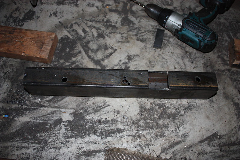
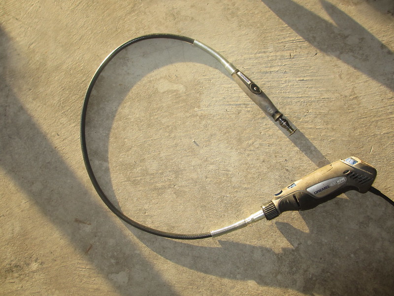
On XJs there is a piece of metal in the passenger side frame that is welded in. I typically notch my frame inserts to go over it, but I realized with the sliders welded to the bumper I couldn’t raise the insert enough to clear that metal piece and get it into the groove. I had to figure out a way to cut that piece out. I finally found a use for this dremmel attachment!
8629281070_c5976fb170_c.jpg


8629280200_90557ce671_c.jpg


Alright, then it was time to clean up for the last time! … And then I realized I wanted to brace the hitch and make some chain hookups…
8629283856_5887d31c0a_c.jpg


And I decided to re-box the driver’s side insert; if you don’t relocate the fuel fillup point to go over the frame then you have to notch it down to slide under that tunnel. I’m sure this was completely unessary, but I like the way it turned out:
8629281726_cdd1ac225e_c.jpg


ALRIGHT, now, all cleaned up and ready for paint!
8629282640_bd01392c26_c.jpg


8629282296_5e317c40ea_c.jpg


8628166367_c4a99b8633_c.jpg


This was the first time I had ever used a flapwheel and REALLY tried to make a piece of metal look good before I painted it. It did not turn out perfectly, but I’m very pleased with the results.
 
Funny thing, I was in such a rush to get some things finished up for a family trip and Rubicon run that I never got any painted pics… So I just went outside and snapped a couple – sorry these are pretty crappy but you get the idea:
9387520337_9f9aef167d_c.jpg


9390300158_fedd325be9_c.jpg


She took some real punishment on the Rubicon, the sliders were pretty much parallel to the rear panels, but I smashed my flairs into some rocks and tweaked the sheetmetal some, which caused it to pull up and away from the sliders, especially on my drivers side:
9390298150_8968a83574_c.jpg


9387522333_f6a07441a5_c.jpg


As you know, the crazy thing about uni-body rigs, they FLEX at the “frame”… I’ve been meaning to plate the front and rear to match my center plating… here you can see how much it moves – enough to scratch the paint!
9390298776_ddc31c6ef2_c.jpg


9390300792_d7cbeecb8b_c.jpg


9390301526_156d077143_c.jpg


9390299432_01c6dd36cd_c.jpg


Final shot of some underneath damage:
9390296156_584297ec2d_c.jpg


Overall I LOVE the bumper. It is nice and high but when I do hit it it’s good and solid. The corners kept me off the rocks with one exception where the rock overhung at the top (and took out my rear light). But I don’t like tail light protectors, so I’ll live with it for now (I do have a plan for the tail lights which will also close the gap between the bottom of them and the bumper.)

This thing took me FOREVER to finish… One day my brother-in-law was admiring it and asking how much I would sell it for. After thinking for a few seconds I said, “20 thousand dollars!” I worked on this silly thing every weekend and spare time during the week for about 2 months. (Yeah, I’m that slow!) At this point I can never sell the XJ because I’d be losing that bumper!
:D
 
Back
Top