XJensen
NAXJA Forum User
- Location
- Sacramento
I decided to put an in cab switch to control the winch from the dash.This way I wont always need to dig out the remote. I did not find anther write up here so here we go.
My goal was to have the switch wired using all five wires in the Warn 5 pin system. The switch would work identical to the remote and also have a second switch to cut the power to the switch and the remote terminal when off.
I have a Warn M8000 but the setup is very similar in other winches. There are several variations on wiring up the switch and I will mention some as I go. There are also kits available if you want to go that route.
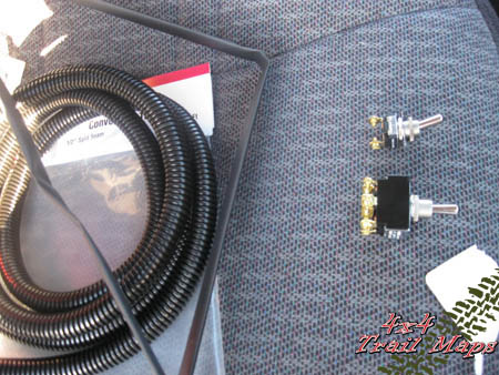
I bought everything I needed at my local electronics and hardware stores. I picked up the following:
2 foot length of 1/2" shrink tube
10' roll of 1/2" split loom, to contain the wires
on off switch
one switch guard
DPDT momentary switch, (on) off (on)
10' - 12' length of trailer wire
10' - 12' length of lamp or speaker wire
wire connectors and fittings
I spent around $30.
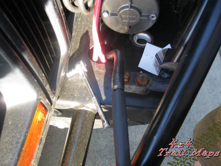
I used the split loom for everything except from under the bumper to the winch. I wanted the new bundle of wires to hide among the others and the large heat shrink tube did the trick.
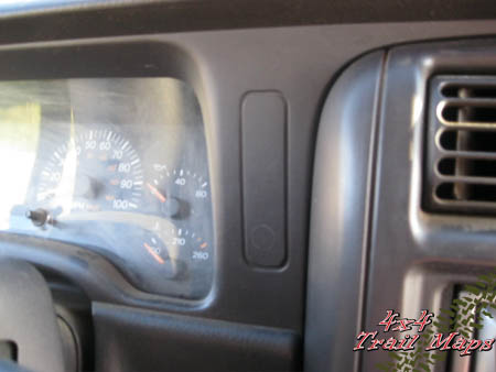
I marked and drilled two 1/2" holes in the dash for the switch. There was nothing behind the scored plastic piece shown next to the instrument panel
I was able to save on some wire length by routing the wires under the bumper and up the inside of the drivers side engine bay. The current running to and from the remote and switch are in the 4 amp range so trailer wire was cheap and sufficient for the job. Lamp of speaker wire will make up for the 5th wire in the five pin remote and the last is for the ground return for the remote terminal kill switch.
The sixth wire is only necessary if you would like to kill power to the remote as well as the switch. I also used the common ground from the winch when it is possible to ground directly to the frame within the cab.
A last variation in maintaining a 5 pin switch would be to tap into a local in cab power source. Be sure to add an inline fuse and be mindful of what you tap into.
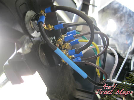
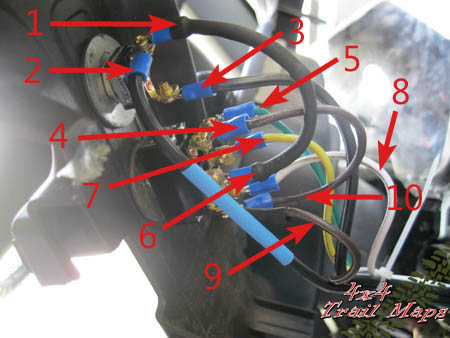
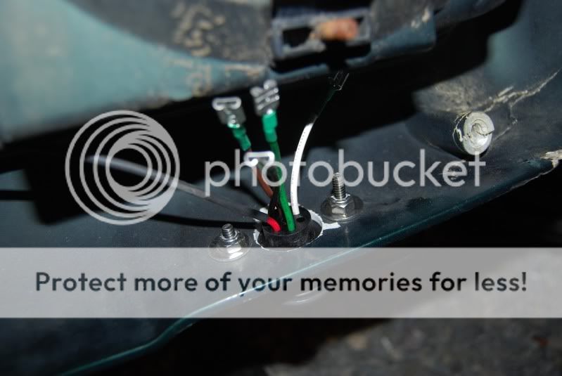
The five wires the go the remote are as follows:
Red - 12V Power
Black - Common Ground
Green - Winch Out
White - Winch in
Brown - Solenoid Ground
I used the same color scheme with the trailer wire with the exception of Yellow for the Red power wire. I used the lamp cord to run the common ground from the winch remote ground (black) to the on off switches off position. I cut this ground to the remote and ran a lead back from the on off switches on position. This cuts the power to the remote unless the in cab kill switch is in the on position. The ground is also sent from the on off switch on position to the DPDT switch.
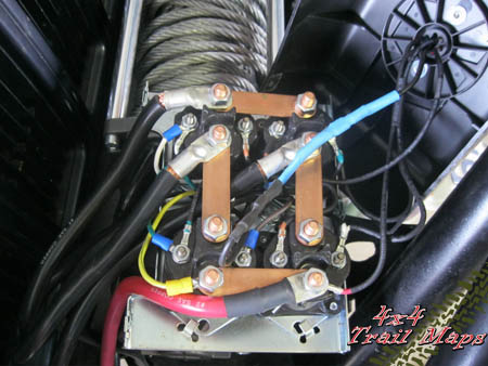
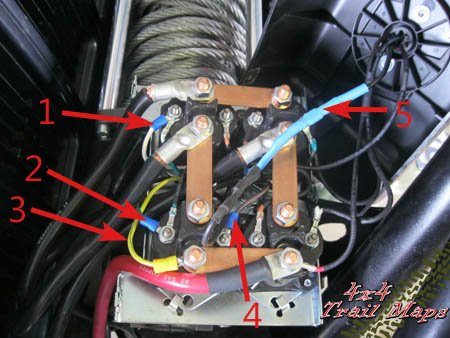
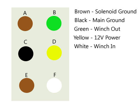
The DPDT switch has six terminals and the following diagram outlines how I wired up the switch. The two brown terminals are bridged together.
My goal was to have the switch wired using all five wires in the Warn 5 pin system. The switch would work identical to the remote and also have a second switch to cut the power to the switch and the remote terminal when off.
I have a Warn M8000 but the setup is very similar in other winches. There are several variations on wiring up the switch and I will mention some as I go. There are also kits available if you want to go that route.
I bought everything I needed at my local electronics and hardware stores. I picked up the following:
2 foot length of 1/2" shrink tube
10' roll of 1/2" split loom, to contain the wires
on off switch
one switch guard
DPDT momentary switch, (on) off (on)
10' - 12' length of trailer wire
10' - 12' length of lamp or speaker wire
wire connectors and fittings
I spent around $30.
I used the split loom for everything except from under the bumper to the winch. I wanted the new bundle of wires to hide among the others and the large heat shrink tube did the trick.
I marked and drilled two 1/2" holes in the dash for the switch. There was nothing behind the scored plastic piece shown next to the instrument panel
I was able to save on some wire length by routing the wires under the bumper and up the inside of the drivers side engine bay. The current running to and from the remote and switch are in the 4 amp range so trailer wire was cheap and sufficient for the job. Lamp of speaker wire will make up for the 5th wire in the five pin remote and the last is for the ground return for the remote terminal kill switch.
The sixth wire is only necessary if you would like to kill power to the remote as well as the switch. I also used the common ground from the winch when it is possible to ground directly to the frame within the cab.
A last variation in maintaining a 5 pin switch would be to tap into a local in cab power source. Be sure to add an inline fuse and be mindful of what you tap into.
The five wires the go the remote are as follows:
Red - 12V Power
Black - Common Ground
Green - Winch Out
White - Winch in
Brown - Solenoid Ground
I used the same color scheme with the trailer wire with the exception of Yellow for the Red power wire. I used the lamp cord to run the common ground from the winch remote ground (black) to the on off switches off position. I cut this ground to the remote and ran a lead back from the on off switches on position. This cuts the power to the remote unless the in cab kill switch is in the on position. The ground is also sent from the on off switch on position to the DPDT switch.
The DPDT switch has six terminals and the following diagram outlines how I wired up the switch. The two brown terminals are bridged together.