• Welcome to the new NAXJA Forum! If your password does not work, please use "Forgot your password?" link on the log-in page. Please feel free to reach out to [email protected] if we can provide any assistance.

Battery relocation and power distrabution....

Yes but it's switched via ign switch. So hook at to batt 1, and let isolator/combiner connect the two when ign is on
 
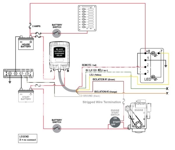
So I was looking at a wiring diagram for an automatic isolating relay... in this case, do you connect the alternator directly to each battery?

fff9e91c-1a8e-4d15-8ef1-8e7d16d9e48c_zpsincrs7eg.jpg


Thanks,
Mike

That just confuses me.

Yes but it's switched via ign switch. So hook at to batt 1, and let isolator/combiner connect the two when ign is on

That just confuses me.

I do want to add the second battery that was recently given to me at some point but atm I just want to move the lead to the back.

Got the parts in:

 
Your wiring diagram is too complicated. Personally I'd not use that isolator/ whatever. A solenoid/relay would be easier, with a wire from ea. post to circuit breakers, then to a SPDT switch, with a lead back to the solenoid. Take ignition wiring out of it.
 
Last edited:
heres what I did, 3 pieces of cutting board, and 3 countersunk 3/8 countersunk bolts(2 to mount it to the fender, 1 for the pos post) have a 1ga welding wire going to it then the 2 factory wires. now also have the wire for the winch to it. no issues the past 2 years and very simple

315997_10200419278457520_1235322258_n.jpg
 
I have a big alt and welding cable so this will be quite helpful when it stops intimidating me.
 
You've Batt. A and Batt.,B with 2 positive leads to ea. side of a HD solenoid. From the posts of the solenoid run two wires to 2 circuit breakers. The circuit breakers to a SPDT switch or on-off-on, whereas the 2 "on" posts will be powered by ea. battery. The center "off" post will be the lead back to a solenoid, when you need to utilize both batteries. Leave the ignition out of it. IMHO.
 
Here is a great thread with 50 pages of info, I used the basic dual battery schematic, but instead of ign control, my setup is controlled with a DPDT on-off-on switch. Its on(ign)-off-on(aux batt) So the switch to the left will join the batts whenever the ign is on. Off is isolated no matter what, on to the right is joined no matter what.

http://www.expeditionportal.com/for...ke-a-cheap-isolated-dual-battery-setup-for-50


Many topics in that thread:
.winching
.breakers vs fuses
.batt types
.cabling
.location
wet, agm, gel
and so forth
 
Last edited:
So working on this today and it occurred to me that the 0/1 isn't going to attach easily to the alt.


How do you guys put that big lug on there? Cut the plastic shield? Stud bolted to it that spaces it off? My alt is a bitch to get to so the easy solution to me would be to make a stud or make a lug out of steel that fits.....
 
If you remove the nut, the plastic piece comes right off. Then you can just put a non-conductive washer or two on the stud.

Yea After I posted I headed to ace with the spare alt and noticed the nut.....
 
This got shelved again. Found my front leaf spring mounts collapsing so had to address that and then my son's 98 blew the motor. I think I have everything to do it except the grommets to pass the wire through. Sourcing them locally has proven to be difficult in this small southern town.... :bawl:
 
I finally got this done over the weekend.


I did run into one issue. There is a black wire on my 94 that seems to be a + cable. It's not hooked up to anything atm because I'm going to trace it and see where it goes. It comes out of the wire loom near the alternator.
 
Back
Top