tbburg
NAXJA Forum User
- Location
- Scottsdale AZ
Montana Auto & Fabrication - AW-4 Transmission Override.
http://www.montanafab.com/aw4_trany_overide.php

This is exactly how it comes, all parts included.
First, how it performs: Exactly as it says. 1-2 shift control without engine codes. It does almost the same thing as a manual override switch installed in the early models. There is a difference. This controller doesn't shut down the TCU like the manual switches we normally use. The switch pulls power from the TCU harness, but doesn't shut power off to the computer when it's engaged. It also won't override the transmission in Drive or 3rd gear. I tried it in 3rd from about 40 - no reaction.(I didn't check to see if the trans would shift normally, I just wanted to see if there was going to be a safety issue if it was accidentally engaged on the highway
At $150.00, it's a little on the pricy side, so the obvious question: Is it worth the price? This is kind of like having a Lawyer write a letter for you. He'll charge you 500 bucks to write the letter, and the price breakdown is something like: write letter: $5.00. Knowing what to put in letter: $495.00. These guys pulled down a late model Cherokee and figured out what signals needed to be mimicked, or whatever it does, and put together a unit that does it. So there's probably 30-50 bucks of hardware in the controller, and I paid 100 - 120 bucks for their time in figuring out how to do it.
My installation is on a '00 XJ sport.
Some of this was already posted in another thread:
http://www.naxja.org/forum/showthread.php?t=1007683&highlight=Montana+fab
I included all of the info here for people who didn't see the first thread.
When I talked to them on the phone, they said they keep them in stock,(that's a good sign!)and ship out same day. Purchased on Thursday, sitting in the office on Monday('had 'em ship it to where I work) It came in a priority mail box(USPS) with a $4.95 stamp on it. They charged me 5 bucks for S+H, so that seems pretty fair.
First impressions out of the box: Very good documentation, 4 pages of instructions including early and late model hookup, as well as for the '93 ZJ Grand Cherokee, which also had the AW-4. Another page containing diagrams and charts for pin-out on the early and late computer connector plugs. Also paper templates for drilling/installation.
The harness/controller is high quality construction, and looks a little more complex then the average 1-2 switch. As I understand it, a wired switch is usually 6 wires(3in, 3 out) on a DP/DT switch. This rotary switch appears to be a Quad pole/Triple Throw. It also has 10 wires coming out of the base of the board. It's also lighted and dim-able with the dash lights(might explain a few of those wires)
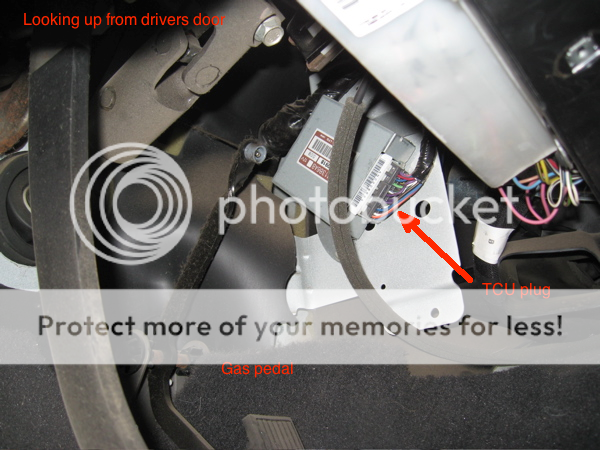
I was a little surprised when I tore into the Jeep. I've read that the ECU in the OBD-2 systems controls the transmission, however, there was a separate TCU mounted just above and to the side of the Gas pedal. Just as well, I wasn't thrilled about hacking into the engine control harness.
Tools I used:
wire cutters
wire strippers
crimping pliers
Philips screw driver
3/8" driver bit(radio removal)
Drill
1/16" drill bit
#4 Irwin Unibit
Multi-tester(to track down dash light circuit)
Sand paper
Sharpie ink marker.
Razor knife
Pop rivet puller
Install: I followed the instructions almost to the letter, except for one cosmetic item, and everything went smoothly. I only came across 2 minor problems, which I'll discuss in the text.
I shouldn't have to say it, but disconnect the battery before you start.
Noob tec:
If you've never pulled the dash apart on a late-model.
Order of disassembly:
Radio/heat control bezel: Put the truck in neutral, gently pull/pry the bottom ends of the bezel out(snaps in place) then work your way up to sides. One snap lock at each corner.
Lower dash cover: Under column, three screws across bottom. Top edge snaps out.
Steel plate(under cover): 2 screws at the top on either side of the column, the bottom has 2 tabs that fit slots in the bottom of the dash.
Light switch knob. There is a small button on the right side of the otherwise smooth switch body. Hold the button down and pull on the knob(might have to twist a little also) until you feel the button move under your finger. Release the button, and the knob will slide the rest of the way out.
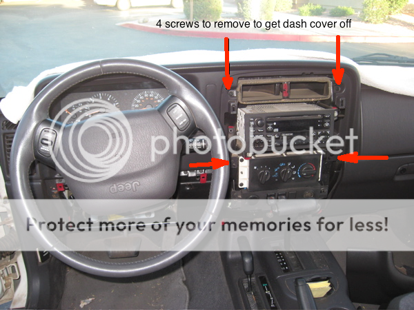
Dash surround: Four screws around the radio/upper AC ducts. Here's a pic
The instrument cluster surround snaps out. There is a glove/boot around the column, attached to the dash. This separates at the bottom and comes off with the dash surround. Put the column in it's lowest position, hold it down and pull the column adjust lever toward the steering wheel. This will give enough clearance to pull the dash surround up and away from the dash.
Radio removal(after the trim bezel is off): 2 hex screws (3/8")and it slides out. (Radio comes out later.)
Uni-bits come in handy for drilling the holes. If you've never used one, they have a straight flute(no spiral)and don't grab and pull through when drilling like a conventional bit. This works great in plastic and thin aluminum sheet. They also self de-bur the hole as you finish drilling. The next step chamfers the hole nicely Conveniently, the #4 Irwin uni-bit goes clear up to 7/8", and covers all the drilling needed. If you don't already have them, save yourself some money and buy the multipack(3 bits) You'll find a lot of uses for these.
Back to work:
Couple pics of the controller:
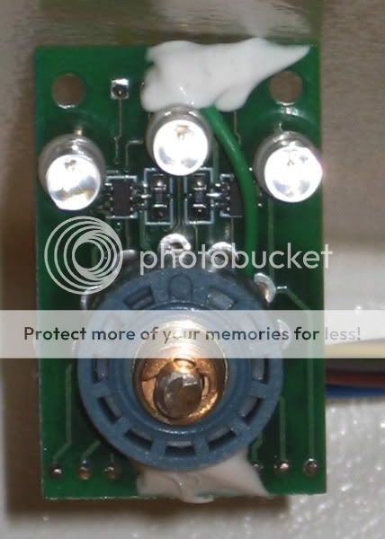
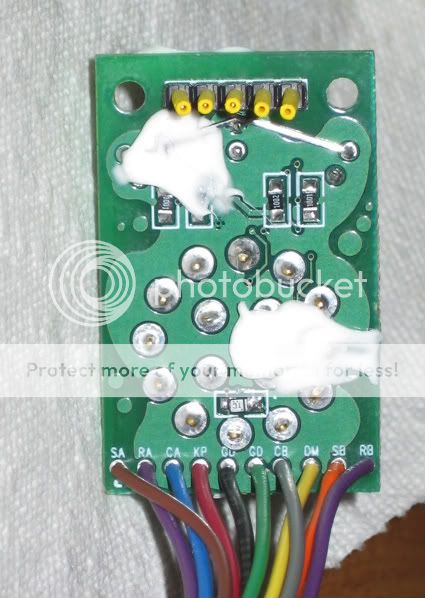
To the people who wanted high res photos of the board: As you can see there's white goop on both sides of the board, and on closer inspection, it appears there are components under there. It seems to be for insulation.
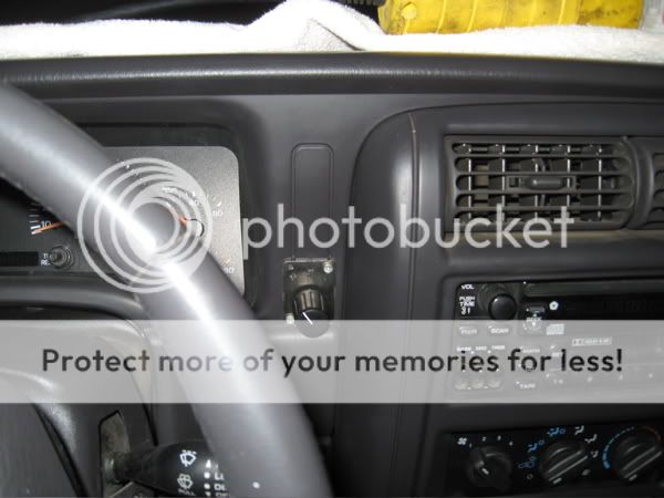
I decided to mount the controller on the dash very close to the location shown in the pics on their web site. I moved mine lower because I intend to have a GPS mounted above that area later on. I put it about 1/16" above the bottom edge of the of the panel next to the instrument cluster.
Here's their mount:

Here's mine:
First problem: while preparing to drill the dash, I noticed the supplied template was a little off. Might be a printing or scaling error. It would probably have worked anyway, but I market the holes using the switch mounting plate with a sharpie. Center drilled all the holes 1/16", checked against the faceplate, then drilled everything out with a Unibit.
My newly butchered dash:
Because of the location of the resistors,(mount on the metal plate under the dash cover) I just set them on the panel and marked the holes rather then use the supplied template. 'Center drilled all the holes with a 1/16' bit, checked against the mount plate, then drilled to size with a 1/8th.
'Used 320 grit sandpaper to clean the resistor mounting surface, then used the supplied pop rivets to secure the resistors to the plate.
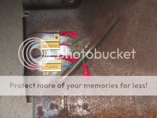
A small container of thermal compound is supplied with the kit, and the backs of the resistors get covered with a thin coat before final install. Careful with the thermal compound. It appears to have some of the same mess inducing characteristics as anti-seize, and the small amount contained in the kit may be enough to paint your whole car.
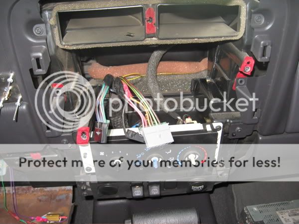
I spliced in the control harness following the instructions included. Very complete instructions. You have to be a bit of a contortionist to do this part. There's only a couple inches of slack on the late model harness, so you have to splice it all in under the dash. Unfortunately, this also makes it impossible to get really good pics.
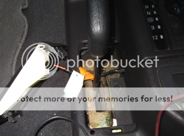
Here's the TCU and harness:
Four cut wires on the TCU harness. and a total of 6 splices are made
pin 12(white wire) solenoid I control. It's cut and routed to the controller, and a wire back from the controller is spliced into the harness
pin 13(orange/white)solenoid 2 control. Same as above, cut and routed to the controller, and a wire back from the controller is spliced into the harness
pin 24(black/tan) Ground wire.
pin 26(blue/white). Ignition switch output (power to the computer, I assume)
There are 2 blue/white wires on the connector, and it's well covered in the instructions which one to use.
That's the first and second wires from the bottom of the plug on the outside of the connector, and the first and 3rd from the bottom on the inside. The second wire on the inside is pink. Don't cut the pink wire.
Here's the finished work:
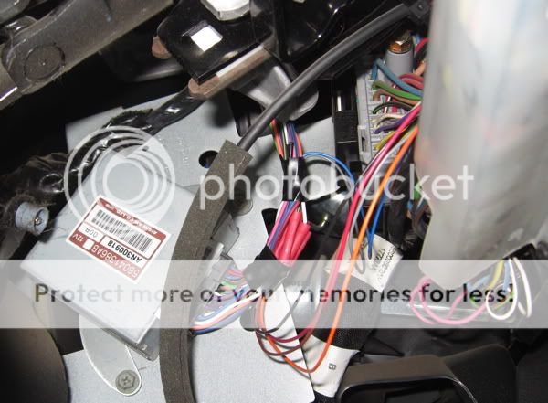
Interestingly, there is no connection to the speed sensors.(pins 1,2,3,&4 on the plug)
There are 3 wires in the controller harness that route to the resistors, and this is where I ran into the second problem. There are female spade connectors already crimped onto the resistors. Male spade terminals are included in the kit. You're supposed to cut the harness to length, then crimp and plug in the wires. Two of the three spade terminals wouldn't connect. They don't appear to be crushed, and I'm not sure what the problem was, but they wouldn't seat more then 1/8th inch. I had a box of connectors in the garage, so I just replaced them. I haven't talked to Montana Fab about this yet, and I'm not worried or upset, but I will let them know about the problem in case they got a box of faulty connectors.
http://www.montanafab.com/aw4_trany_overide.php
This is exactly how it comes, all parts included.
First, how it performs: Exactly as it says. 1-2 shift control without engine codes. It does almost the same thing as a manual override switch installed in the early models. There is a difference. This controller doesn't shut down the TCU like the manual switches we normally use. The switch pulls power from the TCU harness, but doesn't shut power off to the computer when it's engaged. It also won't override the transmission in Drive or 3rd gear. I tried it in 3rd from about 40 - no reaction.(I didn't check to see if the trans would shift normally, I just wanted to see if there was going to be a safety issue if it was accidentally engaged on the highway
At $150.00, it's a little on the pricy side, so the obvious question: Is it worth the price? This is kind of like having a Lawyer write a letter for you. He'll charge you 500 bucks to write the letter, and the price breakdown is something like: write letter: $5.00. Knowing what to put in letter: $495.00. These guys pulled down a late model Cherokee and figured out what signals needed to be mimicked, or whatever it does, and put together a unit that does it. So there's probably 30-50 bucks of hardware in the controller, and I paid 100 - 120 bucks for their time in figuring out how to do it.
My installation is on a '00 XJ sport.
Some of this was already posted in another thread:
http://www.naxja.org/forum/showthread.php?t=1007683&highlight=Montana+fab
I included all of the info here for people who didn't see the first thread.
When I talked to them on the phone, they said they keep them in stock,(that's a good sign!)and ship out same day. Purchased on Thursday, sitting in the office on Monday('had 'em ship it to where I work) It came in a priority mail box(USPS) with a $4.95 stamp on it. They charged me 5 bucks for S+H, so that seems pretty fair.
First impressions out of the box: Very good documentation, 4 pages of instructions including early and late model hookup, as well as for the '93 ZJ Grand Cherokee, which also had the AW-4. Another page containing diagrams and charts for pin-out on the early and late computer connector plugs. Also paper templates for drilling/installation.
The harness/controller is high quality construction, and looks a little more complex then the average 1-2 switch. As I understand it, a wired switch is usually 6 wires(3in, 3 out) on a DP/DT switch. This rotary switch appears to be a Quad pole/Triple Throw. It also has 10 wires coming out of the base of the board. It's also lighted and dim-able with the dash lights(might explain a few of those wires)
I was a little surprised when I tore into the Jeep. I've read that the ECU in the OBD-2 systems controls the transmission, however, there was a separate TCU mounted just above and to the side of the Gas pedal. Just as well, I wasn't thrilled about hacking into the engine control harness.
Tools I used:
wire cutters
wire strippers
crimping pliers
Philips screw driver
3/8" driver bit(radio removal)
Drill
1/16" drill bit
#4 Irwin Unibit
Multi-tester(to track down dash light circuit)
Sand paper
Sharpie ink marker.
Razor knife
Pop rivet puller
Install: I followed the instructions almost to the letter, except for one cosmetic item, and everything went smoothly. I only came across 2 minor problems, which I'll discuss in the text.
I shouldn't have to say it, but disconnect the battery before you start.
Noob tec:
If you've never pulled the dash apart on a late-model.
Order of disassembly:
Radio/heat control bezel: Put the truck in neutral, gently pull/pry the bottom ends of the bezel out(snaps in place) then work your way up to sides. One snap lock at each corner.
Lower dash cover: Under column, three screws across bottom. Top edge snaps out.
Steel plate(under cover): 2 screws at the top on either side of the column, the bottom has 2 tabs that fit slots in the bottom of the dash.
Light switch knob. There is a small button on the right side of the otherwise smooth switch body. Hold the button down and pull on the knob(might have to twist a little also) until you feel the button move under your finger. Release the button, and the knob will slide the rest of the way out.
Dash surround: Four screws around the radio/upper AC ducts. Here's a pic
The instrument cluster surround snaps out. There is a glove/boot around the column, attached to the dash. This separates at the bottom and comes off with the dash surround. Put the column in it's lowest position, hold it down and pull the column adjust lever toward the steering wheel. This will give enough clearance to pull the dash surround up and away from the dash.
Radio removal(after the trim bezel is off): 2 hex screws (3/8")and it slides out. (Radio comes out later.)
Uni-bits come in handy for drilling the holes. If you've never used one, they have a straight flute(no spiral)and don't grab and pull through when drilling like a conventional bit. This works great in plastic and thin aluminum sheet. They also self de-bur the hole as you finish drilling. The next step chamfers the hole nicely Conveniently, the #4 Irwin uni-bit goes clear up to 7/8", and covers all the drilling needed. If you don't already have them, save yourself some money and buy the multipack(3 bits) You'll find a lot of uses for these.
Back to work:
Couple pics of the controller:
To the people who wanted high res photos of the board: As you can see there's white goop on both sides of the board, and on closer inspection, it appears there are components under there. It seems to be for insulation.
I decided to mount the controller on the dash very close to the location shown in the pics on their web site. I moved mine lower because I intend to have a GPS mounted above that area later on. I put it about 1/16" above the bottom edge of the of the panel next to the instrument cluster.
Here's their mount:
Here's mine:
First problem: while preparing to drill the dash, I noticed the supplied template was a little off. Might be a printing or scaling error. It would probably have worked anyway, but I market the holes using the switch mounting plate with a sharpie. Center drilled all the holes 1/16", checked against the faceplate, then drilled everything out with a Unibit.
My newly butchered dash:
Because of the location of the resistors,(mount on the metal plate under the dash cover) I just set them on the panel and marked the holes rather then use the supplied template. 'Center drilled all the holes with a 1/16' bit, checked against the mount plate, then drilled to size with a 1/8th.
'Used 320 grit sandpaper to clean the resistor mounting surface, then used the supplied pop rivets to secure the resistors to the plate.
A small container of thermal compound is supplied with the kit, and the backs of the resistors get covered with a thin coat before final install. Careful with the thermal compound. It appears to have some of the same mess inducing characteristics as anti-seize, and the small amount contained in the kit may be enough to paint your whole car.
I spliced in the control harness following the instructions included. Very complete instructions. You have to be a bit of a contortionist to do this part. There's only a couple inches of slack on the late model harness, so you have to splice it all in under the dash. Unfortunately, this also makes it impossible to get really good pics.
Here's the TCU and harness:
Four cut wires on the TCU harness. and a total of 6 splices are made
pin 12(white wire) solenoid I control. It's cut and routed to the controller, and a wire back from the controller is spliced into the harness
pin 13(orange/white)solenoid 2 control. Same as above, cut and routed to the controller, and a wire back from the controller is spliced into the harness
pin 24(black/tan) Ground wire.
pin 26(blue/white). Ignition switch output (power to the computer, I assume)
There are 2 blue/white wires on the connector, and it's well covered in the instructions which one to use.
That's the first and second wires from the bottom of the plug on the outside of the connector, and the first and 3rd from the bottom on the inside. The second wire on the inside is pink. Don't cut the pink wire.
Here's the finished work:
Interestingly, there is no connection to the speed sensors.(pins 1,2,3,&4 on the plug)
There are 3 wires in the controller harness that route to the resistors, and this is where I ran into the second problem. There are female spade connectors already crimped onto the resistors. Male spade terminals are included in the kit. You're supposed to cut the harness to length, then crimp and plug in the wires. Two of the three spade terminals wouldn't connect. They don't appear to be crushed, and I'm not sure what the problem was, but they wouldn't seat more then 1/8th inch. I had a box of connectors in the garage, so I just replaced them. I haven't talked to Montana Fab about this yet, and I'm not worried or upset, but I will let them know about the problem in case they got a box of faulty connectors.