- Location
- Lafayette, CA
Homemade Winch Bumper V1.0
http://www.naxja.org/forum/showthread.php?t=968021
Over the last couple of years my Jeep has progressed to the point where I am now starting to be limited by the front approach angle, and my rather large monstrosity of a front winch bumper. At the time I built it, I felt I was cutting edge by cutting the plastic grill out and managed to suck the winch almost 2’’ closer than anything I had seen and especially anything store bought.
However, it has reached the point where I cannot take this bumper any more, for both small issues I have with it and how much it hurts my approach angle.
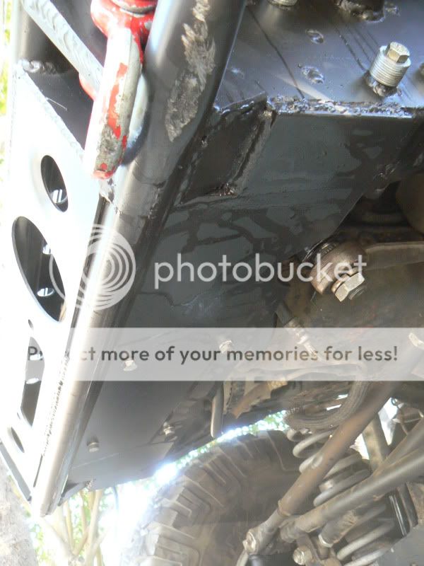
Major Issue 1:Steering box reinforcement
I have always been plagued with steering box issues. Several years ago before I knew better and didn’t have my outer frame rail reinforced I managed to pull all three of my steering box bolt through the frame resulting in one heck of a 16 hour day on the trail. Next came last year when I broke one of the tabs off of the steering box which ended my wheeling trip within the first hour.
Lower rear bolt:
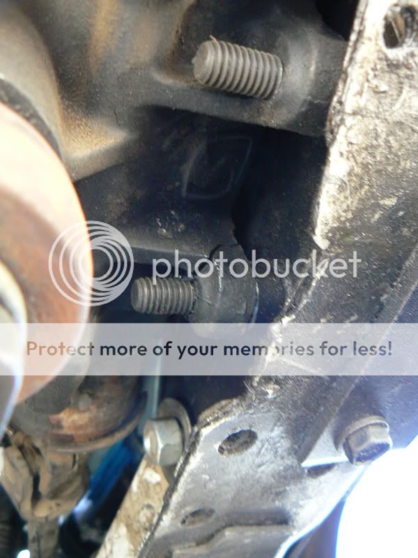
This year I managed to sheer a grade 8 bolt in Moab (thankfully on the last day on the last obstacle on the last trail) and decided Ive had enough.
Hells Revenge, Escalator:
http://www.facebook.com/photo.php?p...09803#!/video/video.php?v=421526299889&ref=mf
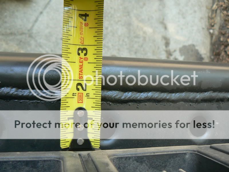
Major Issue 2: Approach Angle
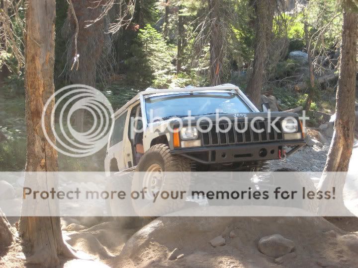
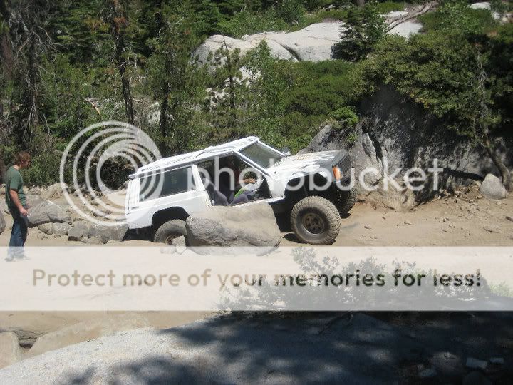
While at the time I thought I did a pretty good job and maintaining a good approach angle, as I became more willing to try harder trails and harder lines I soon realized that my bumper was always dragging or being hit on one thing or another.
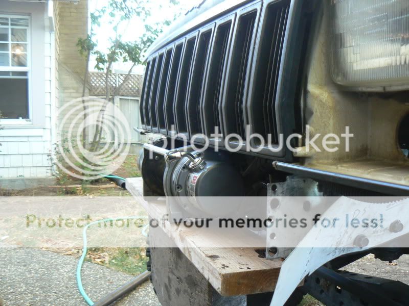
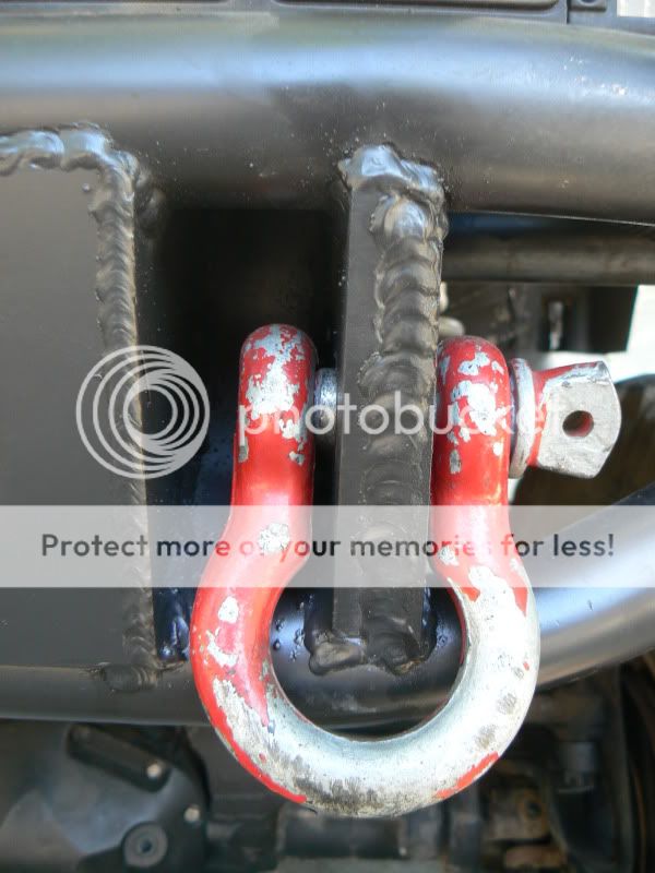
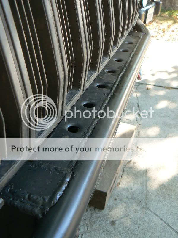
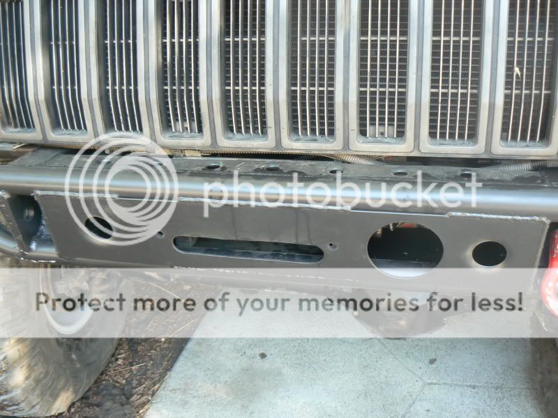
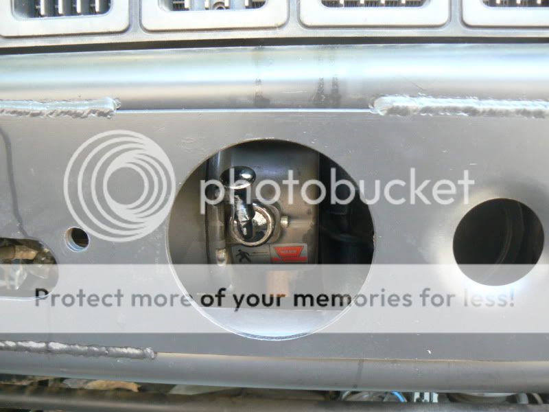
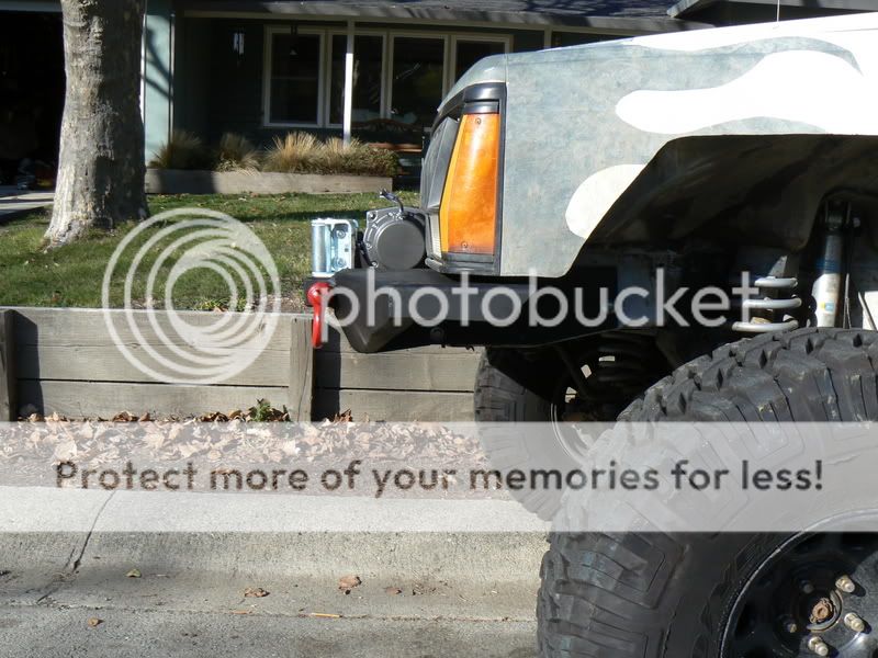
Here you can see just how far it stuck out. 6’’ from the face of the grill to the face of the winch, and 8’’ to the shackle mounts.
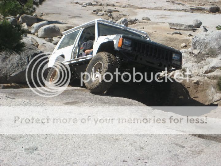
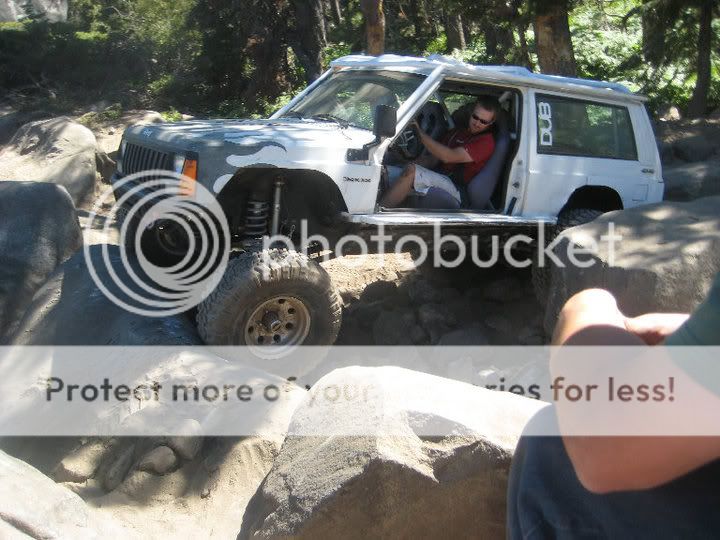
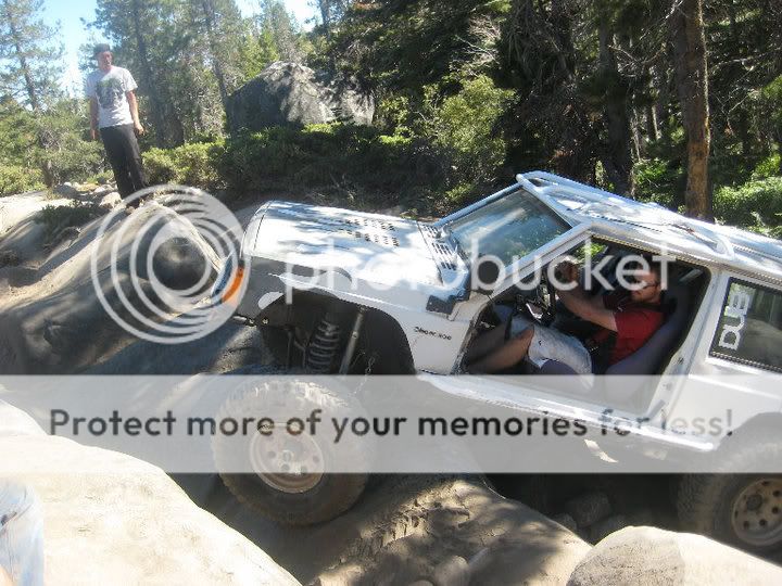
And here is an example of why even that is to much

How to build a winch bumper without sacrificing approach angle and strengthening the steering box mounts
What Im doing is nothing new, Im actually copying several different people, just with my own little twist. This however, is not a bumper for the weak hearted or one afraid of a little body modification.
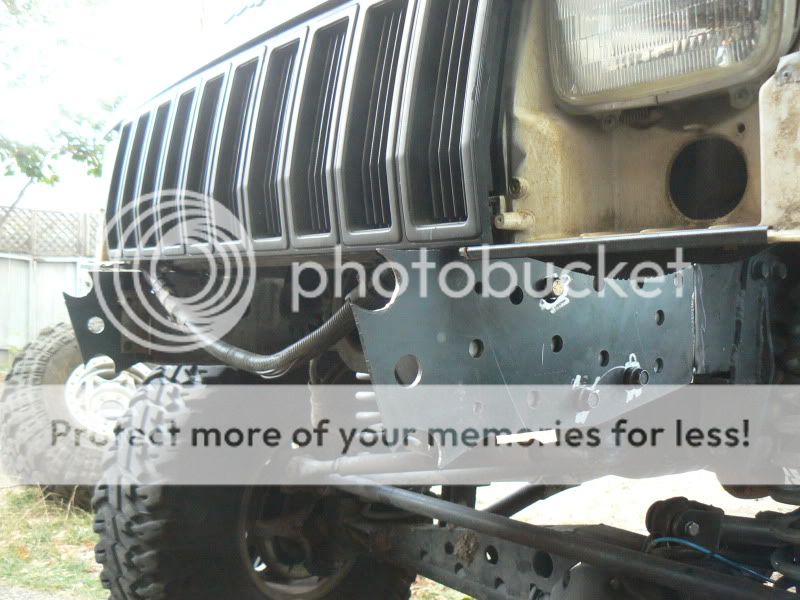
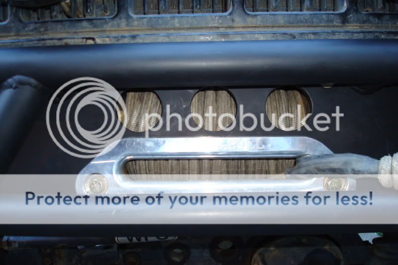
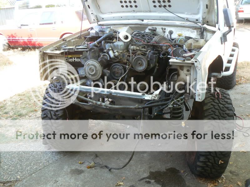
Step one was to remove the V1.0 bumper, and remove the entire front clip including radiator. This might be a good time to also mention that while my Jeep originally came with AC it has since been removed so the condenser is no longer there.
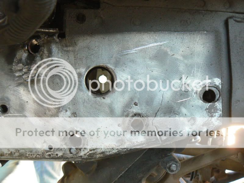
Ive seen pictures of cracked unibodies all the time, but figured that only happens to people other than myself. Well, turns out a unibody starts to break down if you try and turn anything larger than the stock sized tires.
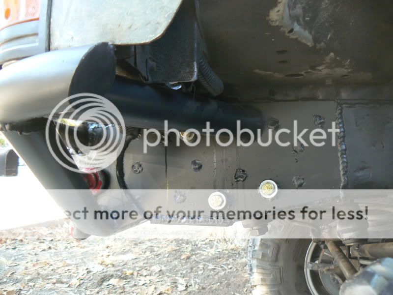
Crack #1 located just behind the rearmost steering box bolt
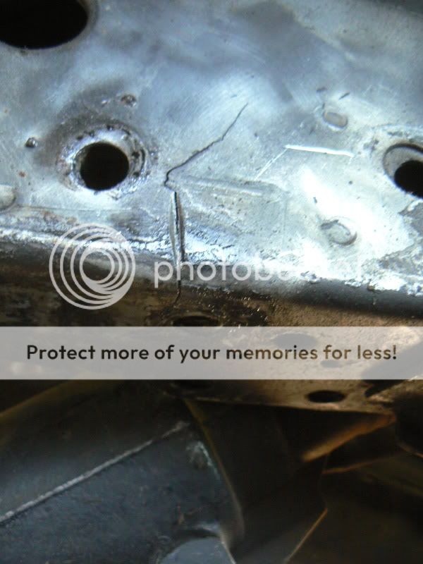
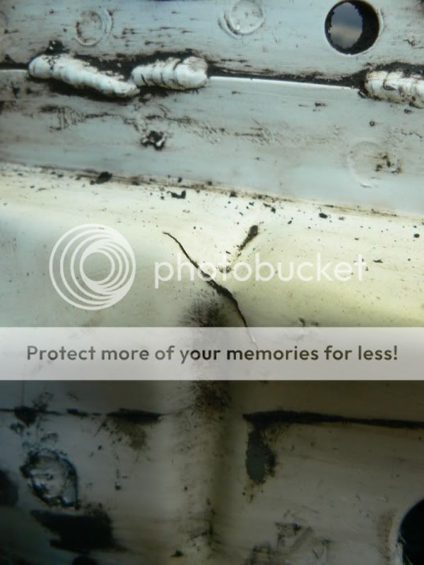
Crack #2 located on the inner side of the framerail
While building V1.0 bumper I assumed that the stock frame sleeves through the frame were strong enough to support the steering box. This turned out to not be the case as it turns out I managed to crush the framerail by almost ½’’ and bend my Custom4x4 inner steering box brace.
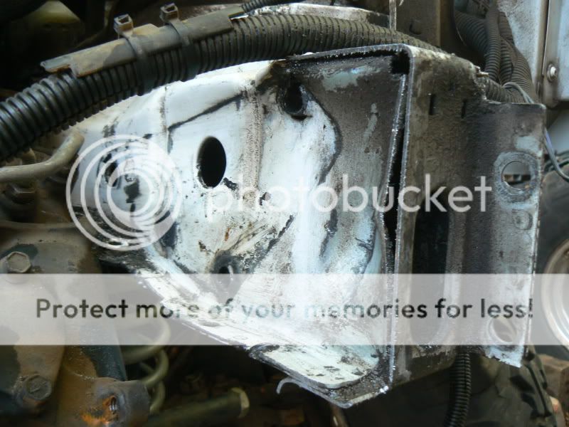
If you take anything away from this thread, just remember that the stock sleeves are not strong enough for hard wheeling!
Onto the fun stuff!
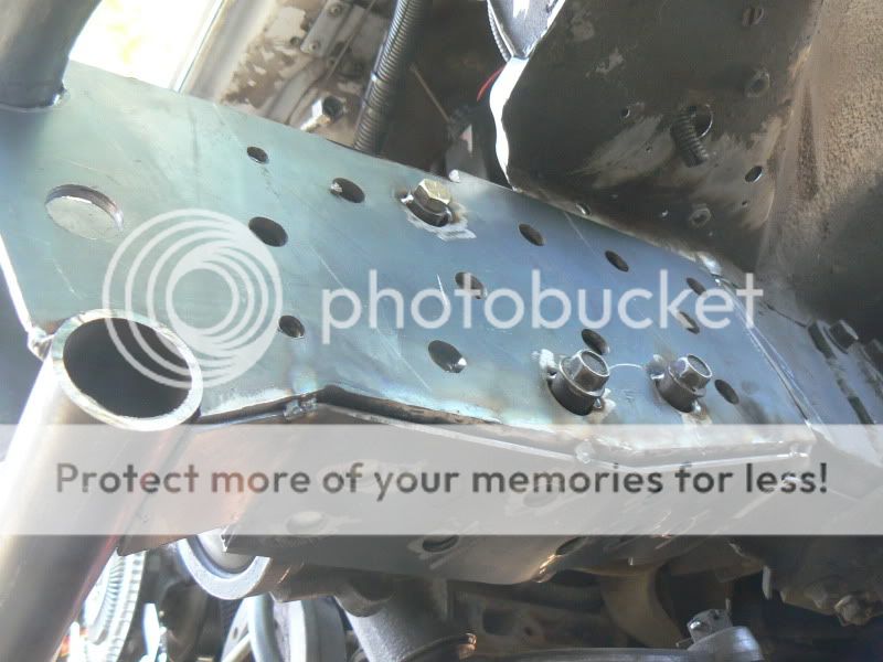
Take your sawzall and make that first cut. Remember, the first one is always the hardest. Your goal is to remove the front crossmember that is exactly in the wrong spot for tucking a winch back as far as possible .
I was actually surprised at how little the framerails moved after that first cut. For a Jeep that has been wheeled fairly regularly and up until recently didn’t have a rollcage, they only separated ¼’’ at most.
Remove that entire crossmember, making sure to keep the rubber bushings the radiator mounts with.

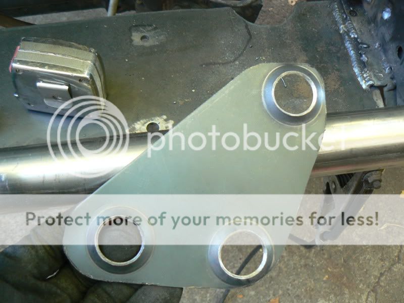
I ended up removing the sides of the crossmember that overlap the framerails by simply drilling out the spot welds and grinding a couple of the welds on top. Originally I thought it would be stronger if I kept “caps” intact but I realized that I can redo them bigger and better.
Just for a little FYI, the stock steering box sleeves do not just fall out. They are held on by a lot of little spot welds and voodoo magic. Try as I might, I couldn’t get them out, and finally gave up in fear of messing the frame rail up more than I already had.
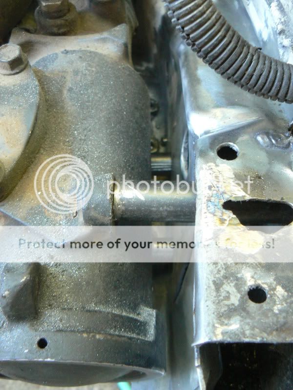
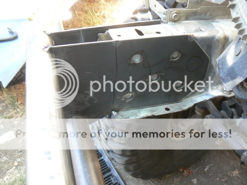
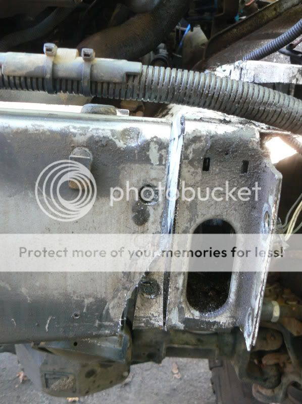
Here are some picture of the inside of the framerail, both drivers side and passenger side. Looks like the threaded holes that the stock sway bar uses are actually the same part as the lower steering box sleeves. The upper hole was on its own, and the bolt that the factory and a lot of aftermarket tow hooks use is its own bracket/sleeve assembly.
DS

(Note: Jeep originally came with factory ATF lubricated drivers side framerail to cut down on rust)
PS

Both brackets share the three nuts, looks like the drivers side has the sleeves welded onto it. Also note on the passenger side how the back bolt hole is in fact its own bracket.
If someone has figure out how to take those blasted things out, let us know, but I was unable to short of taking a plasma cutter to my Jeep and decided to just work around them.
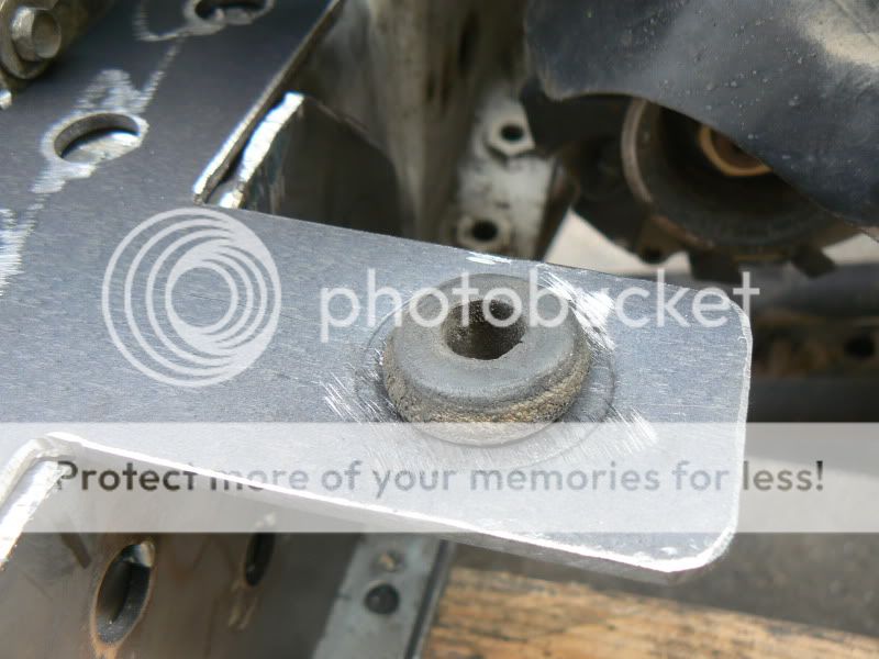
Since this bumper build basically started because of my last wheeling trip and sheering a steering box bolt in half, I decided to work on fixing that as the first step of reconstruction.
http://www.naxja.org/forum/showthread.php?t=968021
Over the last couple of years my Jeep has progressed to the point where I am now starting to be limited by the front approach angle, and my rather large monstrosity of a front winch bumper. At the time I built it, I felt I was cutting edge by cutting the plastic grill out and managed to suck the winch almost 2’’ closer than anything I had seen and especially anything store bought.
However, it has reached the point where I cannot take this bumper any more, for both small issues I have with it and how much it hurts my approach angle.
Major Issue 1:Steering box reinforcement
I have always been plagued with steering box issues. Several years ago before I knew better and didn’t have my outer frame rail reinforced I managed to pull all three of my steering box bolt through the frame resulting in one heck of a 16 hour day on the trail. Next came last year when I broke one of the tabs off of the steering box which ended my wheeling trip within the first hour.
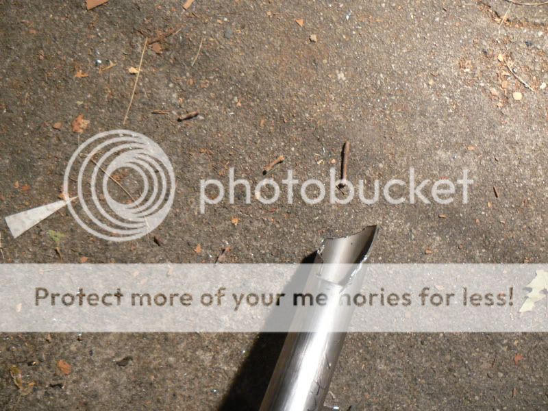
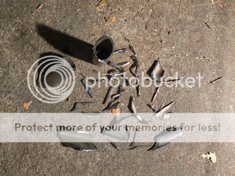
Lower rear bolt:
This year I managed to sheer a grade 8 bolt in Moab (thankfully on the last day on the last obstacle on the last trail) and decided Ive had enough.
Hells Revenge, Escalator:
http://www.facebook.com/photo.php?p...09803#!/video/video.php?v=421526299889&ref=mf
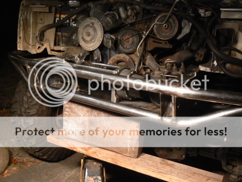
Major Issue 2: Approach Angle
While at the time I thought I did a pretty good job and maintaining a good approach angle, as I became more willing to try harder trails and harder lines I soon realized that my bumper was always dragging or being hit on one thing or another.
Here you can see just how far it stuck out. 6’’ from the face of the grill to the face of the winch, and 8’’ to the shackle mounts.
And here is an example of why even that is to much
How to build a winch bumper without sacrificing approach angle and strengthening the steering box mounts
What Im doing is nothing new, Im actually copying several different people, just with my own little twist. This however, is not a bumper for the weak hearted or one afraid of a little body modification.
Step one was to remove the V1.0 bumper, and remove the entire front clip including radiator. This might be a good time to also mention that while my Jeep originally came with AC it has since been removed so the condenser is no longer there.
Ive seen pictures of cracked unibodies all the time, but figured that only happens to people other than myself. Well, turns out a unibody starts to break down if you try and turn anything larger than the stock sized tires.
Crack #1 located just behind the rearmost steering box bolt
Crack #2 located on the inner side of the framerail
While building V1.0 bumper I assumed that the stock frame sleeves through the frame were strong enough to support the steering box. This turned out to not be the case as it turns out I managed to crush the framerail by almost ½’’ and bend my Custom4x4 inner steering box brace.
If you take anything away from this thread, just remember that the stock sleeves are not strong enough for hard wheeling!
Onto the fun stuff!
Take your sawzall and make that first cut. Remember, the first one is always the hardest. Your goal is to remove the front crossmember that is exactly in the wrong spot for tucking a winch back as far as possible .
I was actually surprised at how little the framerails moved after that first cut. For a Jeep that has been wheeled fairly regularly and up until recently didn’t have a rollcage, they only separated ¼’’ at most.
Remove that entire crossmember, making sure to keep the rubber bushings the radiator mounts with.
I ended up removing the sides of the crossmember that overlap the framerails by simply drilling out the spot welds and grinding a couple of the welds on top. Originally I thought it would be stronger if I kept “caps” intact but I realized that I can redo them bigger and better.
Just for a little FYI, the stock steering box sleeves do not just fall out. They are held on by a lot of little spot welds and voodoo magic. Try as I might, I couldn’t get them out, and finally gave up in fear of messing the frame rail up more than I already had.
Here are some picture of the inside of the framerail, both drivers side and passenger side. Looks like the threaded holes that the stock sway bar uses are actually the same part as the lower steering box sleeves. The upper hole was on its own, and the bolt that the factory and a lot of aftermarket tow hooks use is its own bracket/sleeve assembly.
DS
(Note: Jeep originally came with factory ATF lubricated drivers side framerail to cut down on rust)
PS
Both brackets share the three nuts, looks like the drivers side has the sleeves welded onto it. Also note on the passenger side how the back bolt hole is in fact its own bracket.
If someone has figure out how to take those blasted things out, let us know, but I was unable to short of taking a plasma cutter to my Jeep and decided to just work around them.
Since this bumper build basically started because of my last wheeling trip and sheering a steering box bolt in half, I decided to work on fixing that as the first step of reconstruction.
Last edited: