• Welcome to the new NAXJA Forum! If your password does not work, please use "Forgot your password?" link on the log-in page. Please feel free to reach out to [email protected] if we can provide any assistance.

ZJ Alternator swap for Renix

Slo-Sho

NAXJA Forum User
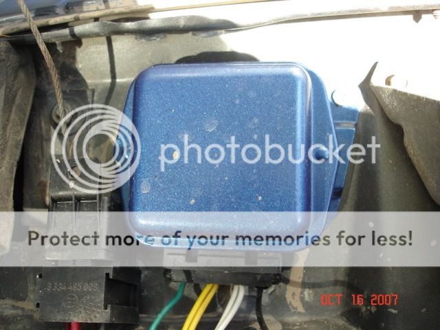
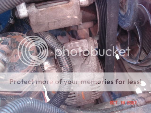
Got my hands on a 136a alternator and external voltage regulator from an unknown vehicle. The voltage regulator has four terminals on it labeled " I A S F" respectively. Does anyone know what these terminals do? Also on the H.O. alternator there are two terminals that are unmarked, what do these do?
 
The two posts (they should be paired, an inch and a half to two inches apart) are for the field connection from the regulator in the PCM. The single post with the shroud is the output to the vehicle, and the ground would attach anywhere to the case (directly) or to the mounting screws.

The difficulty with your swap is that the Delco CS-130 is internally regulated, while the ND alternator is externally regulated. This is easy enough to overcome -

1) Use a Delco wound to a higher output. 130-140A is usually easy for a CS-130 for a competent shop.

2) Use an external regulator with the ND - like the Prestolite I give information for on my site. This does introduce the complication of mounting the ND alternator into Delco brackets - or getting HO brackets to mount the ND from the off.

Given a choice, I tend to prefer Delco units anyhow.
 
From the voltage regulator I believe the 'I' terminal is unused. The A terminal is the voltage when key on. The S and F terminals I believe go to the alternator. My question is on the Denso alternator there are two studs as mentioned above about an 1" apart on the back of the alternator. Does it matter which of these I hook the 'S' and 'F' terminals from the regulator to? Is the alternator polarized?
 
my boss had a 2.5 YJ and he wanted more alt power, so he used the ac bracket area and added another alt (ford). they both have voltage regulators so it won't over charge. they just work when needed. and he had a on/off switch for it. pretty neat.
 
*update*

I got the 97 ZJ 136amp alternator installed into my 90 Renix I6. Let me just say there was alot of material I had to take off the bracket to make the alternator fit the H.O. alt bracket (forget about using the Renix alt. brackets), however it's in there secure. A stock length 97+ xj belt will also be needed.

I used an external regulator from an old Ford truck to control the ZJ alternator. The regulator has 4x terminals on it labeled I A S F. There are also 3x connections that need to be made on the ZJ alt. to make it charge (main output, and two field terminals). On the alternator one of the field terminals goes to ground, doesn't matter which one. The other terminal goes to the F terminal on the regulator. The S and A terminals can be tied together and connected to the Yellow wire from the factory alt. plug. The I terminal is not used. This particular regulator can be sourced at most any auto parts store for less than $15 at this time.

I'm happy to say that with this upgrade my volt gauge is now steady at 14v versus the 100amp CS-130 at comparable vehicle speeds/loads. Hot idle voltage is also improved over the internally regulated unit (wasn't surprised).
 
*edit*

Above I stated that the S and A terminals can be tied together. For maximum longevity of the alternator the S terminal from the external regulator goes to the accessory wire so that it does not see voltage when cranking.

DSC00908.jpg


DSC00907.jpg
 
Last edited:
Good timing. My '88's Alt. is getting a little flaky lately. Thanks for the info, guys.
 
Hello !

I installed regulator for 7 Amp rotors.
I wired it as Slo-Sho described.

After it I have a few question:
It works, but the charging voltage is about 15,8 - 16,0 V - isn't to much?

On the idle motor speed all lights (internal,external) are flashing - easy to notice it. Is it normal? Voltage oscilation are about 0,3 V.

When I increase motor speed winking is less noticeable.
 
I got it - why it happened.

Through A terminal the current goes quite high. Original wiring cannot service such a current - this is the reason why everything winked.

I had to connect "A" connector directly to battery "+".

"S" - terminal must be connected to ignition switch -
It should be hot when the key is on. If you connect "S" terminal to Accessory wiring - it has voltage when is the key ON, but it has no voltage when you are cranking - this is the best way to wire it - during cranking alternator does not load the engine.

Now I have 14,7 volts and it works perfect - maximum power load and voltage is constant
 
Back
Top